Method and apparatus for color image forming capable of effectively forming a quality color image

a color image and color image technology, applied in the field of color image forming, can solve the problems of inability to effectively form inability to achieve the effect of simplifying maintenance pattern management, and forming a quality color imag

Active Publication Date: 2007-06-21
RICOH KK
View PDF19 Cites 32 Cited by
  • Summary
  • Abstract
  • Description
  • Claims
  • Application Information

AI Technical Summary

Benefits of technology

[0010] This patent specification describes a maintenance pattern forming method which can effectively form a quality color image by simplifying maintenance pattern management. In one example, a maintenance pattern forming method includes the steps of conveying, generating, and forming. The conveying step conveys a transfer member on a surface of a conveying member such that there is a spacing area between two adjacent transfer members. The generating step generates a timing signal for at least one of a plurality of colors formed by the color image forming apparatus. The forming step forms at least one pattern onto the spacing area based on the timing signal. The pattern can be, but is not limited to, at least one of a process control pattern, a position adjustment pattern, or a blade curl suppression pattern.
[0011] This patent specification further describes a novel color image forming apparatus which can effectively form a quality color image by simplifying maintenance pattern management. In one embodiment, a color image forming apparatus includes a conveying member, a plurality of image carrying members, a signal generator, and a pattern formation mechanism. The conveying member has a surface to convey a transfer member, the surface including a spacing area between two adjacent transfer members. The plurality of image carrying members are arranged in tandem and carry images. The images are transferred onto the transfer member conveyed by the conveying member. The signal generator generates a timing signal for at least one of a plurality of colors formed by the color image forming apparatus. The pattern formation mechanism forms a pattern on the spacing area based on the timing signal. The pattern can be, but is not limited to, at least one of a process control pattern, a position adjustment pattern, or a blade curl suppression pattern.

Problems solved by technology

However, the above patent document does not describe details relating to a position and a timing at which the density detection pattern is formed.

Method used


Image

  • Method and apparatus for color image forming capable of effectively forming a quality color image
  • Method and apparatus for color image forming capable of effectively forming a quality color image
  • Method and apparatus for color image forming capable of effectively forming a quality color image

Examples


Embodiment Construction

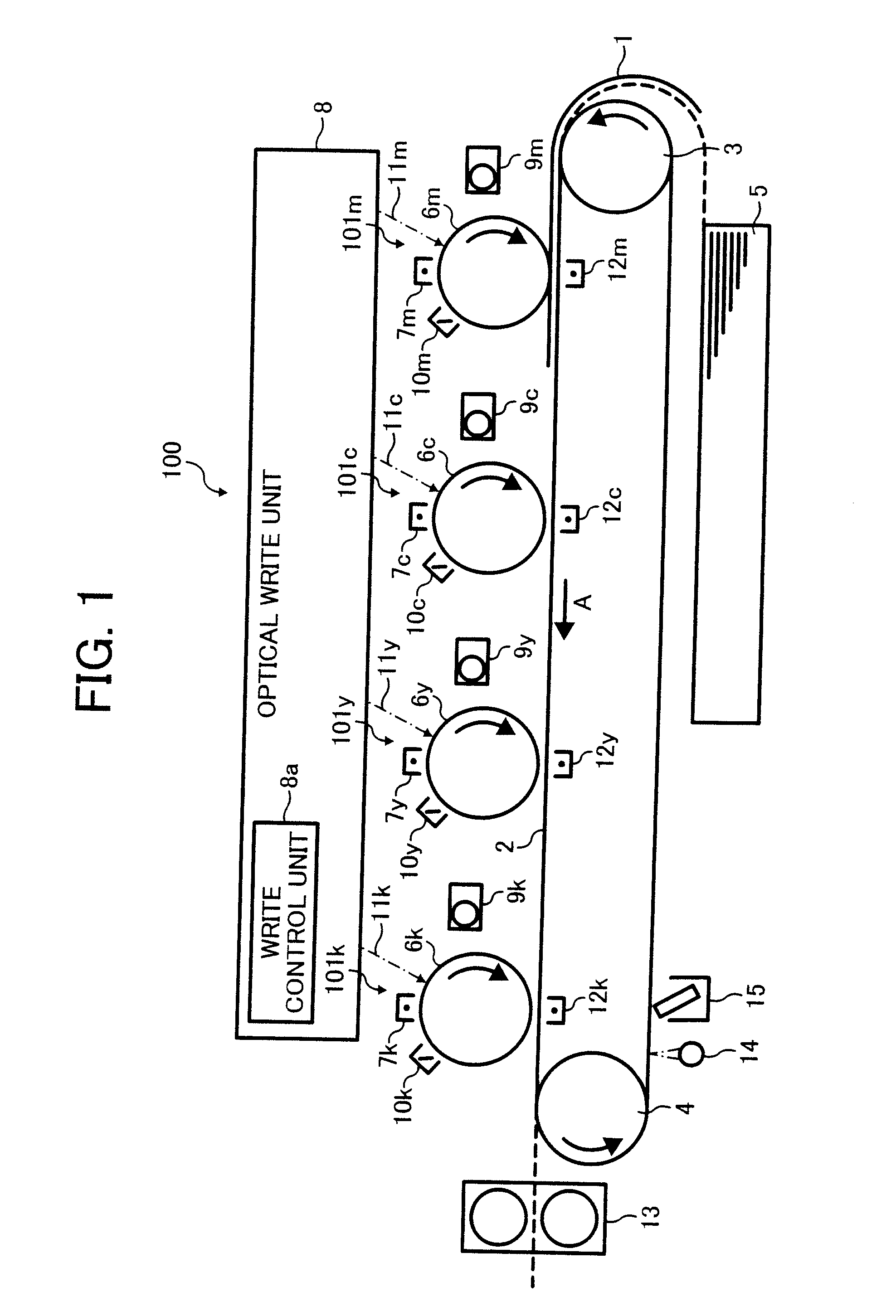
[0018] In describing preferred embodiments illustrated in the drawings, specific terminology is employed for the sake of clarity. However, the disclosure of this patent specification is not intended to be limited to the specific terminology so selected and it is to be understood that each specific element includes all technical equivalents that operate in a similar manner. Referring now to the drawings, wherein like reference numerals designate identical or corresponding parts throughout the several views, particularly to FIG. 1, an image forming apparatus 100 according to an exemplary embodiment of the present invention is described.

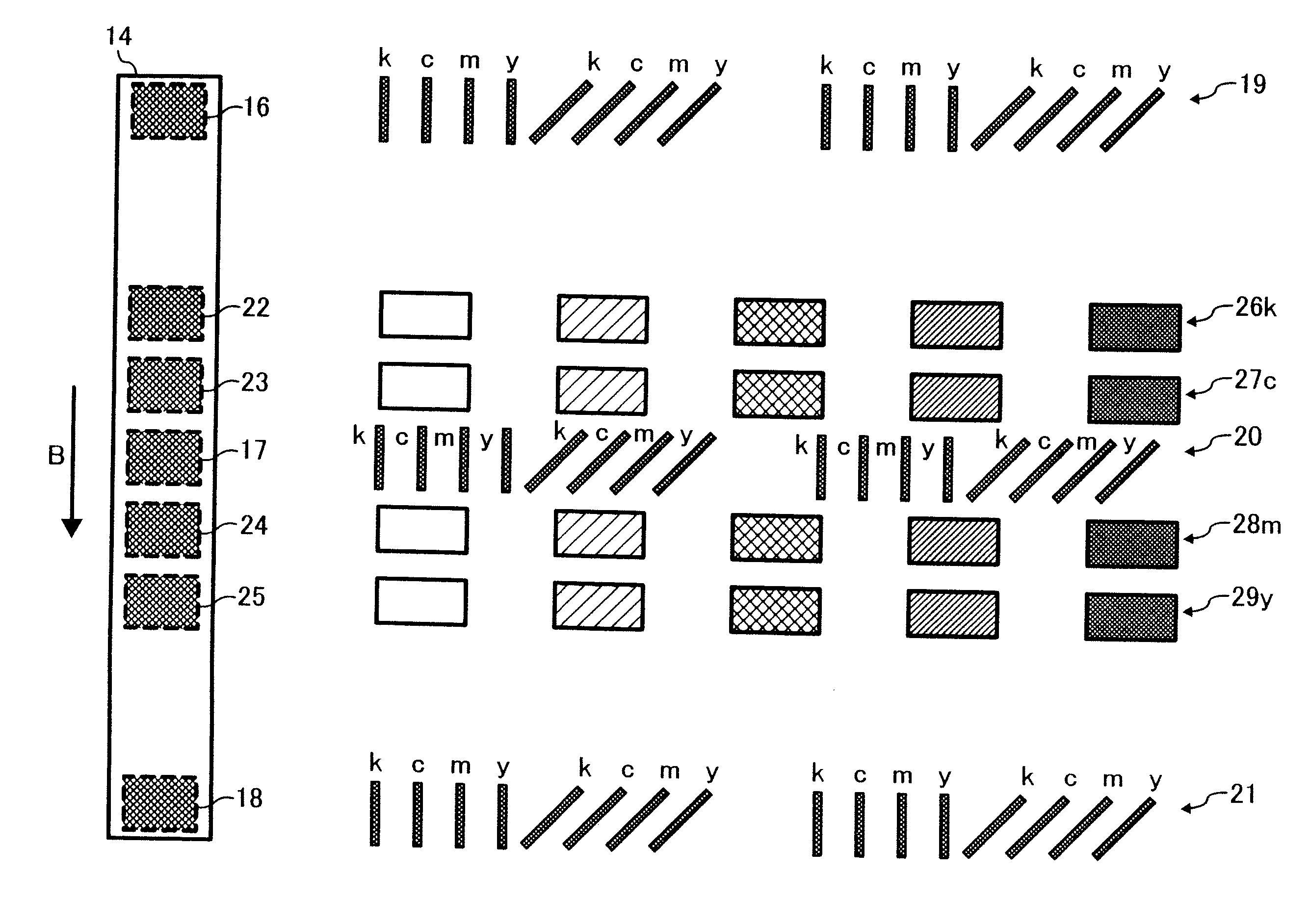
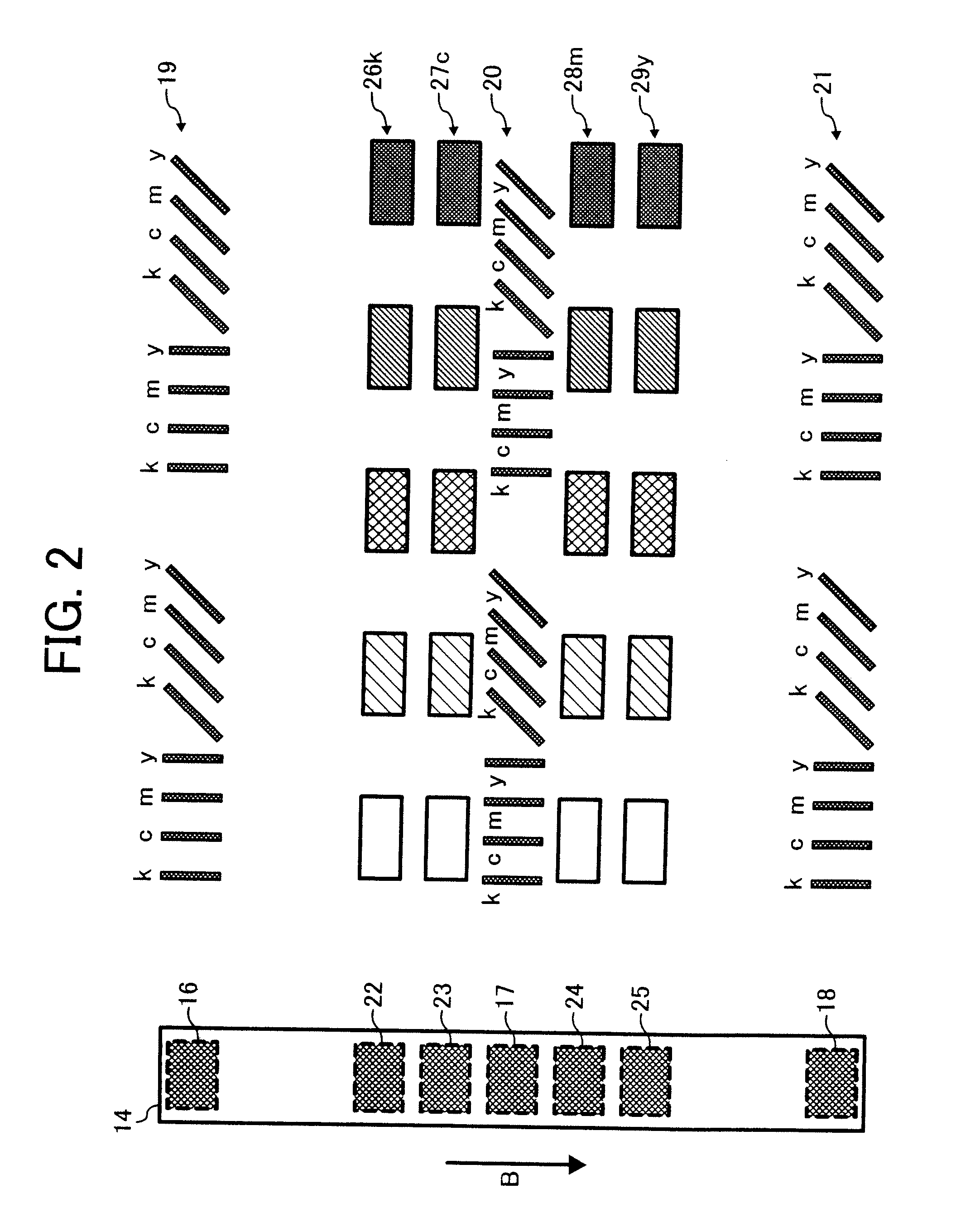
[0019] As illustrated in FIG. 1, the image forming apparatus 100 includes a conveyor belt 2, a drive roller 3, a driven roller 4, a sheet feed tray 5, an optical write unit 8, a fuser 13, a detection sensor 14, and a cleaner 15. The image forming apparatus 100 also includes an image forming mechanism 101m, an image forming mechanism 101c, an image form...


PUM


Abstract

A maintenance pattern forming method includes conveying, generating, and forming. The conveying conveys a transfer member on a surface of a conveying member such that there is a spacing area between two adjacent transfer members on the surface of the conveying member. The generating generates a timing signal for at least one of a plurality of colors formed by a color image forming apparatus. The forming forms at least one of a process control pattern, a position adjustment pattern, and a blade curl suppression pattern onto the spacing area based on the timing signal.

Description

CROSS REFERENCE TO RELATED APPLICATIONS [0001] This patent specification is based on Japanese patent application, No. JP2005-346298 filed on Nov. 30, 2005 in the Japan Patent Office, the entire contents of which are incorporated by reference herein. BACKGROUND OF THE INVENTION [0002] 1. Field of the Invention [0003] The present invention relates to a method and apparatus for color image forming, and more particularly to a method and apparatus for color image forming capable of effectively forming a quality color image by simplifying maintenance pattern management. [0004] 2. Discussion of the Background [0005] As a background, the color image forming apparatus described in Japanese Patent Application Laid-Open No. 2005-91901 is known. The color image forming apparatus described in Japanese Patent Application Laid-Open No. 2005-91901 (hereinafter “background image forming apparatus”) forms density detection patterns on a non-image-formation area of a conveyor belt during continuous pr...

Claims


Application Information

Patent Timeline
Patent Type & Authority Applications(United States)
IPC IPC(8): G03G15/00
CPCG03G15/50G03G15/0194G03G2215/0161
Inventor SHINOHARA, TADASHIKOBAYASHI, SHINJIWATANABE, TAKAOKAIMA, NOBUYOSHISHUKUYA, YUICHIROKAWAI, YOSHIAKISATO, KAZUYUKI
Owner RICOH KK
Why Eureka
Try Eureka