Rotational vacuum assisted resin transfer molding

a vacuum assisted and resin transfer technology, applied in the direction of transportation and packaging, coatings, other domestic articles, etc., can solve the problems of unnecessarily heavy structure, unsatisfactory thickness gradient in the finished structure, and reduce the integrity of the molded structure, so as to reduce the gravity-induced settling of the resin

Active Publication Date: 2007-06-21
THE BOEING CO
View PDF34 Cites 20 Cited by
  • Summary
  • Abstract
  • Description
  • Claims
  • Application Information

AI Technical Summary

Benefits of technology

[0007] According to still another aspect of the invention, apparatus is provided for producing a composite fiber structure comprising a forming tool having the shape of the structure and upon which a laminate layup may be disposed. A mounting assembly is provided for mounting the tool for rotation about a central axis of rotation. An air tight flexible membrane covers the layup and a resin injection system is provided for injecting resin through the membrane into the layup. A vacuum system produces a vacuum within the membrane and urges the resin to pass through composite fibers forming the layup. A motor rotates the tool about the central axis of rotation at a rate which reduces gravity induced settling of the resin in the layup during curing.

Problems solved by technology

When molding relatively large structures, such as an aircraft fuselage, gravitational effects on resin flow behavior can create undesirable thickness gradients in the finished structure.
Thickness gradients due to resin migration not only reduce the integrity of the molded structure, but also result in a structure that is unnecessarily heavy, since in order to achieve a minimum wall thickness at the top of the structure, wall thickness near the bottom of the structure is greater than necessary.
In the case of aircraft structures, thickness gradients of the type described above make it difficult to produce complete fuselage sections having integral stringers and co-bonded fuselage frames.

Method used


Image

  • Rotational vacuum assisted resin transfer molding
  • Rotational vacuum assisted resin transfer molding

Examples


Embodiment Construction

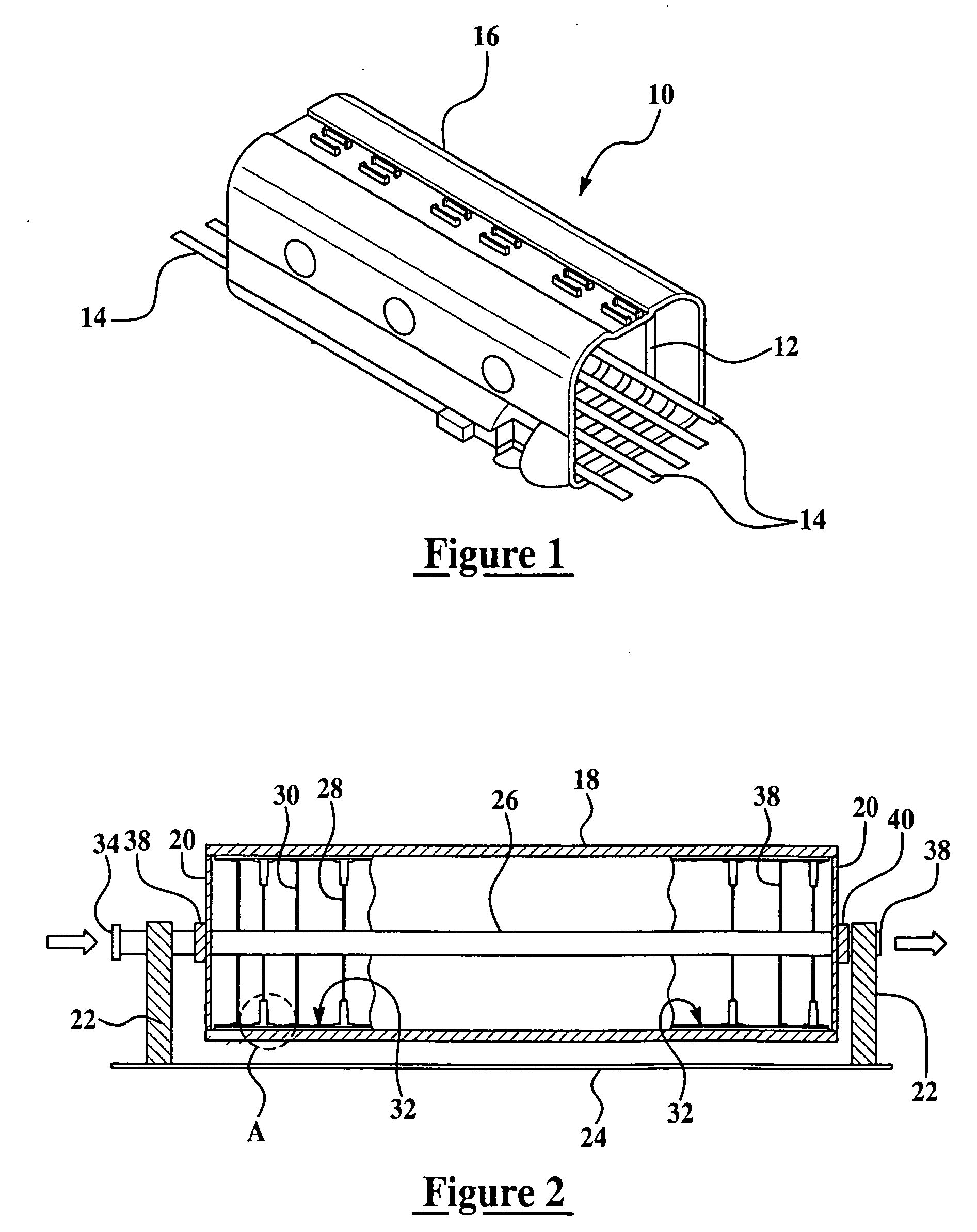
[0013] Referring first to FIG. 1, a section of an aircraft fuselage generally indicated by the numeral 10 is essentially square in cross section and has walls formed from a laminated composite material well known in the art of aircraft construction. The fuselage 10 has an outer skin 16 which is co-bonded with a series of longitudinally spaced, transversely extending frame members 12, and a series of laterally spaced, longitudinally extending stringers 14. The frame members 12, stringers 14 and skin 16 are preferably formed using VARTM, in which these components are co-cured and co-bonded to form a highly rigid, rugged, unitized structure. In accordance with the present invention, the wall thickness of the skin 16 is substantially uniformed throughout the height of the fuselage 10, thus providing a structure which possesses high structural integrity with minimum weight.

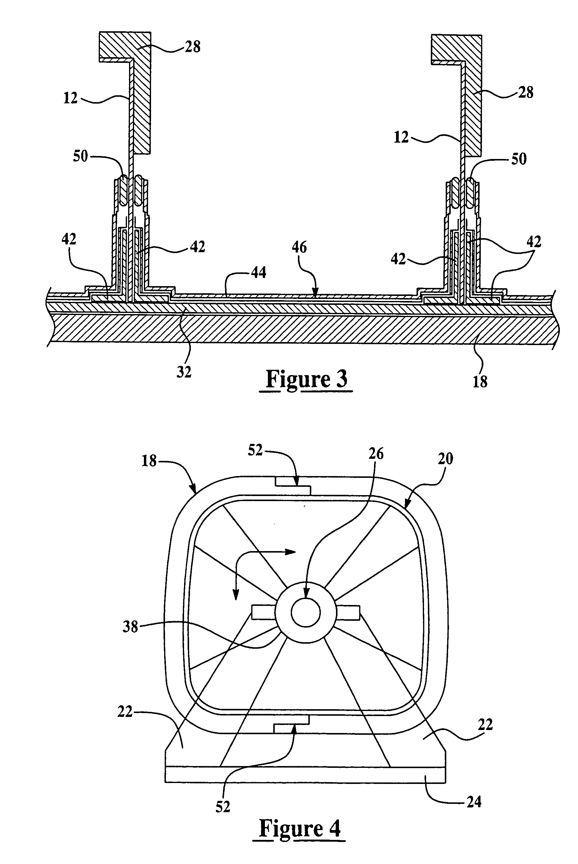
[0014] The fuselage 10, or similar large composite structure, is manufactured using the apparatus shown in FIGS. 2-...


PUM

PropertyMeasurementUnit
pressureaaaaaaaaaa
structureaaaaaaaaaa
gravityaaaaaaaaaa

Abstract

Thickness gradients in large, cobonded composite structures resulting from gravity-induced resin migration during curing is substantially reduced by rotating the structure during the resin infusion and curing stages. The layup for the structure is placed on a rotatable tool fixture and vacuum bagged. The tool fixture is mounted on a central support tube provided with motors for rotating the tool fixture about the axis of the tube. The tube has internal passageways that deliver resin to the bagged layup and carry away excess resin from the layup using vacuum pressure. The resulting composite structures exhibit thickness gradients less than 10%.

Description

FIELD OF THE INVENTION [0001] This invention generally relates to vacuum assisted resin transfer molding, and deals more particularly with a method and apparatus for reducing thickness gradients in molded composite parts caused by gravity-induced settling of the resin during curing. BACKGROUND OF THE INVENTION [0002] Vacuum-assisted resin transfer molding (VARTM) is being used more frequently to mold large composite structures, such as sections of aircraft. VARTM is a variant of traditional resin transfer molding (RTM), possessing advantages over conventional RTM by eliminating matched-metal tooling costs, reducing volatile emissions and allowing for low injection pressures. In VARTM, vacuum pressure is used to force liquid resin into dry composite reinforcements that have been laid in a sealed mold, often in the form of a preform. The mold can be a one sided tool with a vacuum bag, a two sided matched tool with a vacuum seal, or a soft bag enclosing the entire structure to be molde...

Claims


Application Information

Patent Timeline
Patent Type & Authority Applications(United States)
IPC IPC(8): D02G3/00
CPCB29C41/042B29C70/326B29C70/443Y10T428/2933B29L2031/3082B29D99/001B29D99/0014B29C70/32B29C70/44B29C70/446B29C41/04B29C43/12B29C41/047
Inventor KULESHA, RICHARD L.
Owner THE BOEING CO
Why Eureka
Try Eureka