

Electro-Mechanical Interfaces to Mount Robotic Surgical Arms
a robotic surgical arm and electronic mechanical technology, applied in the direction of electrical programme control, coupling device connection, programme control, etc., can solve the problems of time-consuming and difficult to remove the robotic surgical arm for one person
Active Publication Date: 2007-06-21
INTUITIVE SURGICAL OPERATIONS INC
View PDF16 Cites 110 Cited by
- Summary
- Abstract
- Description
- Claims
- Application Information
AI Technical Summary
Benefits of technology
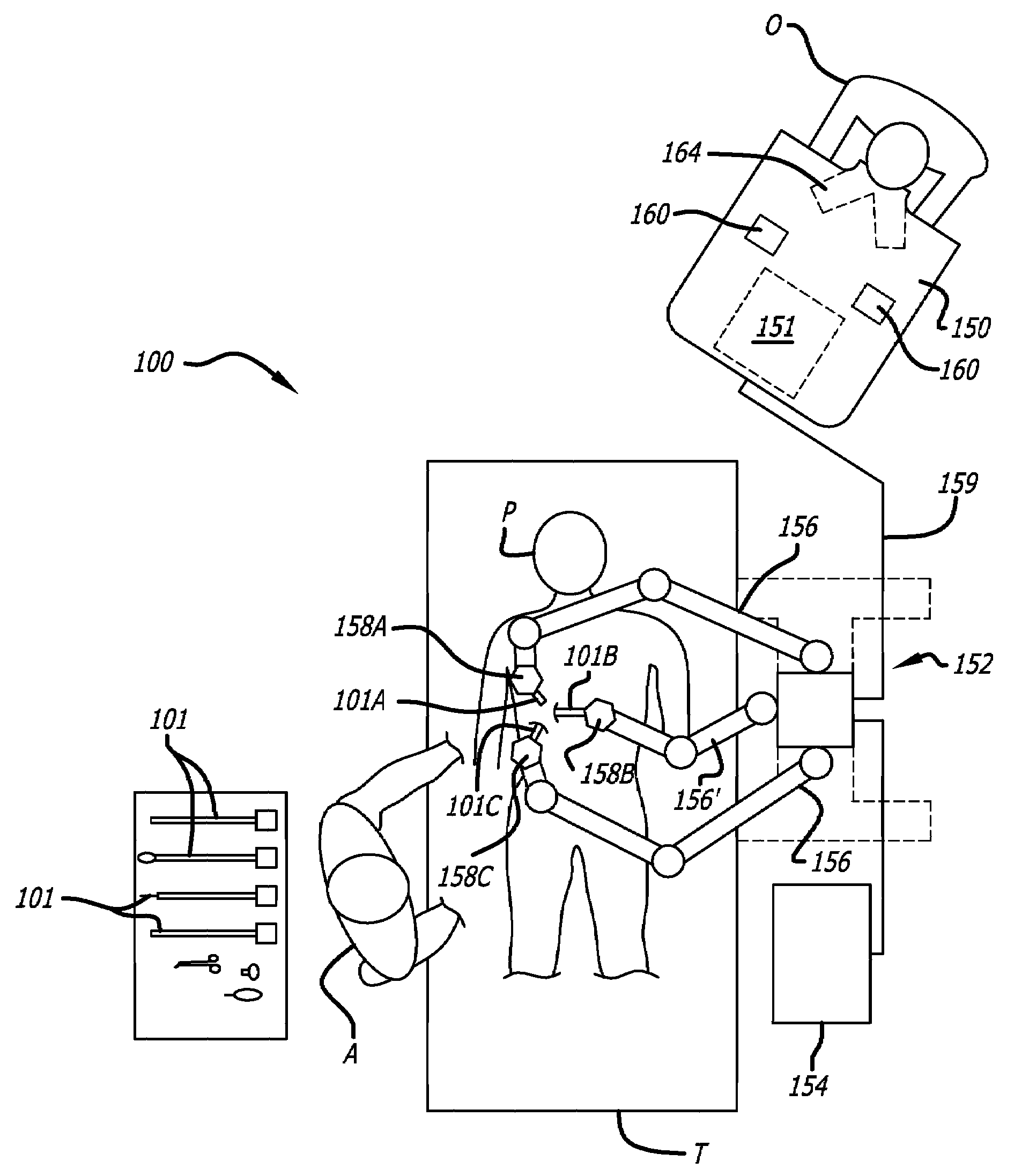
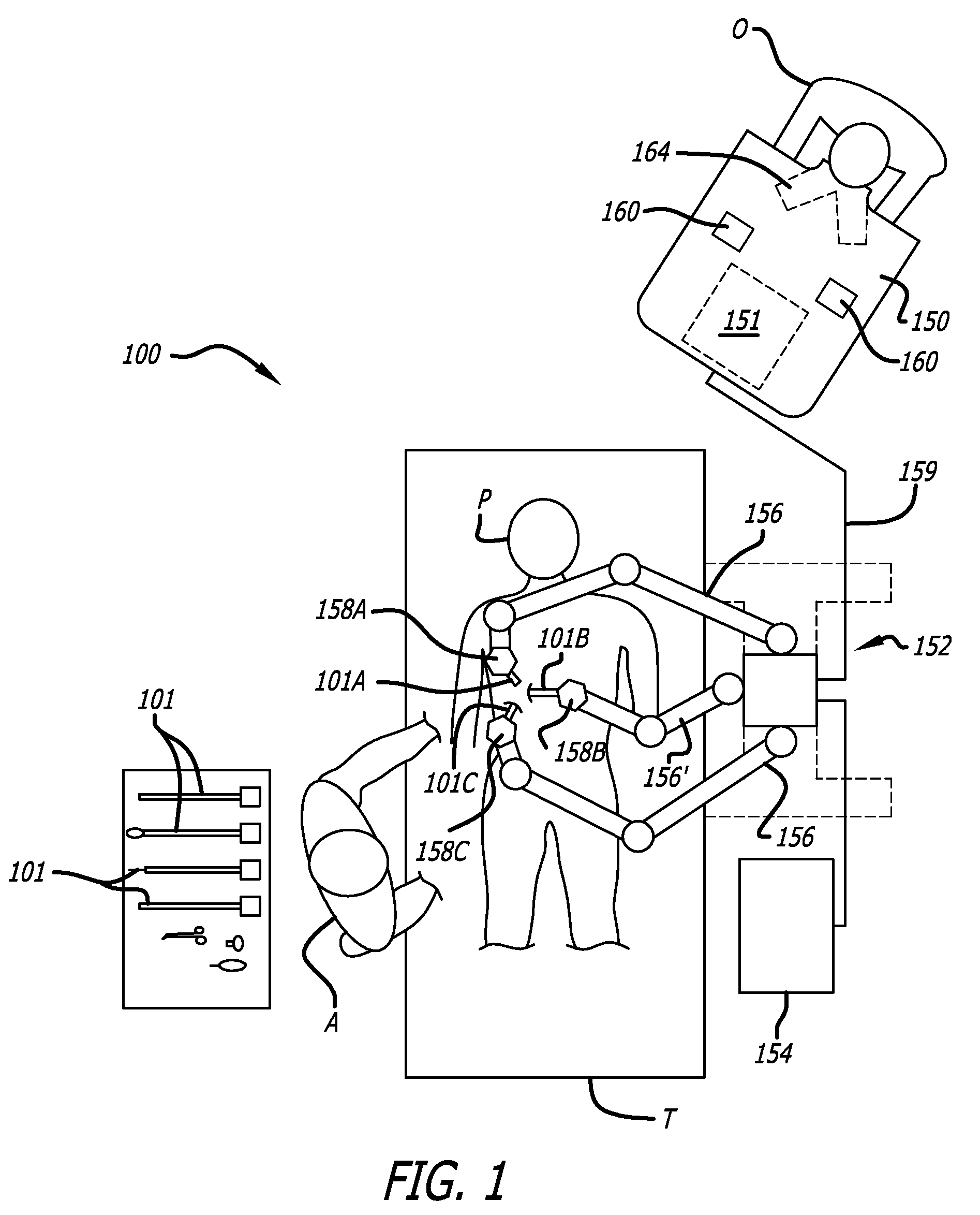
[0005]FIG. 1 is a block diagram of a robotic surgery system to perform minimally invasive robotic surgical procedures using one or more robotic surgical arms with a s
Problems solved by technology
As a typical robotic surgical arm is relatively heavy, swapping out a robotic surgical arm is difficult and time consuming for one person.
Method used
View moreImage
Smart ImageViewing Examples

Examples
first embodiment
[0057]In the invention (FIGS. 10, 11A-11B), electrical connectors 650A and 650B independently float from each other within sliding pockets 1080A and 1080B, respectively.
second embodiment
[0058]In the invention (FIG. 14A), electrical connectors 1401A and 1401B also float independently but require some extra space between the connectors. The electrical connectors 1401A and 1401B are allowed to move by means of floating bushings 1410.
third embodiment
[0059]In the invention (FIG. 14B), a single electrical connector 1450 is a floating electrical connector, which is allowed to move by means of floating bushings 1410.
Login to View More PUM
 Abstract
In one embodiment of the invention, a method of mounting a surgical robotic arm to a set-up arm of a robotic surgical system is provided that includes sliding a pair of guide slots of the surgical robotic arm over a pair of guide tabs in the set-up arm; aligning electrical connectors in the set-up arm to electrical connectors of the surgical robotic arm; and coincidentally mating male electrical connectors to female electrical connectors while finally mating the guide tabs in the set-up arm to flanges of a housing of the surgical robotic arm.
Description
CROSS REFERENCE TO RELATED APPLICATIONS[0001]This non-provisional patent application claims the benefit of U.S. Provisional Patent Application No. 60 / 752,446, entitled “Slidable Electro-Mechanical Interfaces for Mounting Robotic Surgical Arms” filed by William Burbank et al. on Dec. 20, 2005.FIELD[0002]The embodiments of the invention relate generally to robotic surgical systems. More particularly, the embodiments of the invention relate to mounting and dismounting robotic surgical arms to robotic surgical systems and the electro-mechanical interfaces to do so.BACKGROUND[0003]Robotic surgery systems are used to perform minimally invasive robotic surgical procedures. Should one of the robotic surgical arms fail for some reason, it is desirable to replace it as quickly as possible to continue the surgery and / or perform additional procedures. If one of a plurality of robotic surgical arms of the system is not being used, it may be used to swap out the failing arm. Alternatively, a spar...
Claims
Login to View More Application Information
Patent Timeline
 IPC IPC(8): G05B19/04
CPCA61B19/22A61B19/2203A61B19/5212A61B2017/00477A61B2019/2223A61B2019/2242B25J19/0029H01R13/6315H01R13/748H01R35/025A61B34/70A61B34/71A61B90/361A61B34/30A61B34/37C01B3/36C01B2203/025C10J3/00C10J3/20C10J3/721C10J2300/0956C10J2300/0959C10J2300/0969C10J2300/1665C10J2300/1681C10K3/005C10K3/008C12P7/065C12P7/08Y02E50/10Y10T29/53Y02E50/30
InventorBURBANK, WILLIAMLUKE, SCOTTHOORNAERT, DEAN
OwnerINTUITIVE SURGICAL OPERATIONS INC