Inkjet pad printer

a pad printer and inkjet technology, applied in typewriters, printing, duplicating/marking methods, etc., can solve the problems of increasing the number of steps, increasing the time and cost of production, and attending expenses and delays

Inactive Publication Date: 2007-06-28
ILLINOIS TOOL WORKS INC
View PDF11 Cites 21 Cited by
  • Summary
  • Abstract
  • Description
  • Claims
  • Application Information

AI Technical Summary

Problems solved by technology

Printing a new image requires the fabrication of a new cliché plate, with attendant expense and delay.
Another disadvantage of a conventional pad printing system is that because the system applies ink to the entire cliché plate, the system c

Method used


Image

  • Inkjet pad printer
  • Inkjet pad printer
  • Inkjet pad printer

Examples


Embodiment Construction

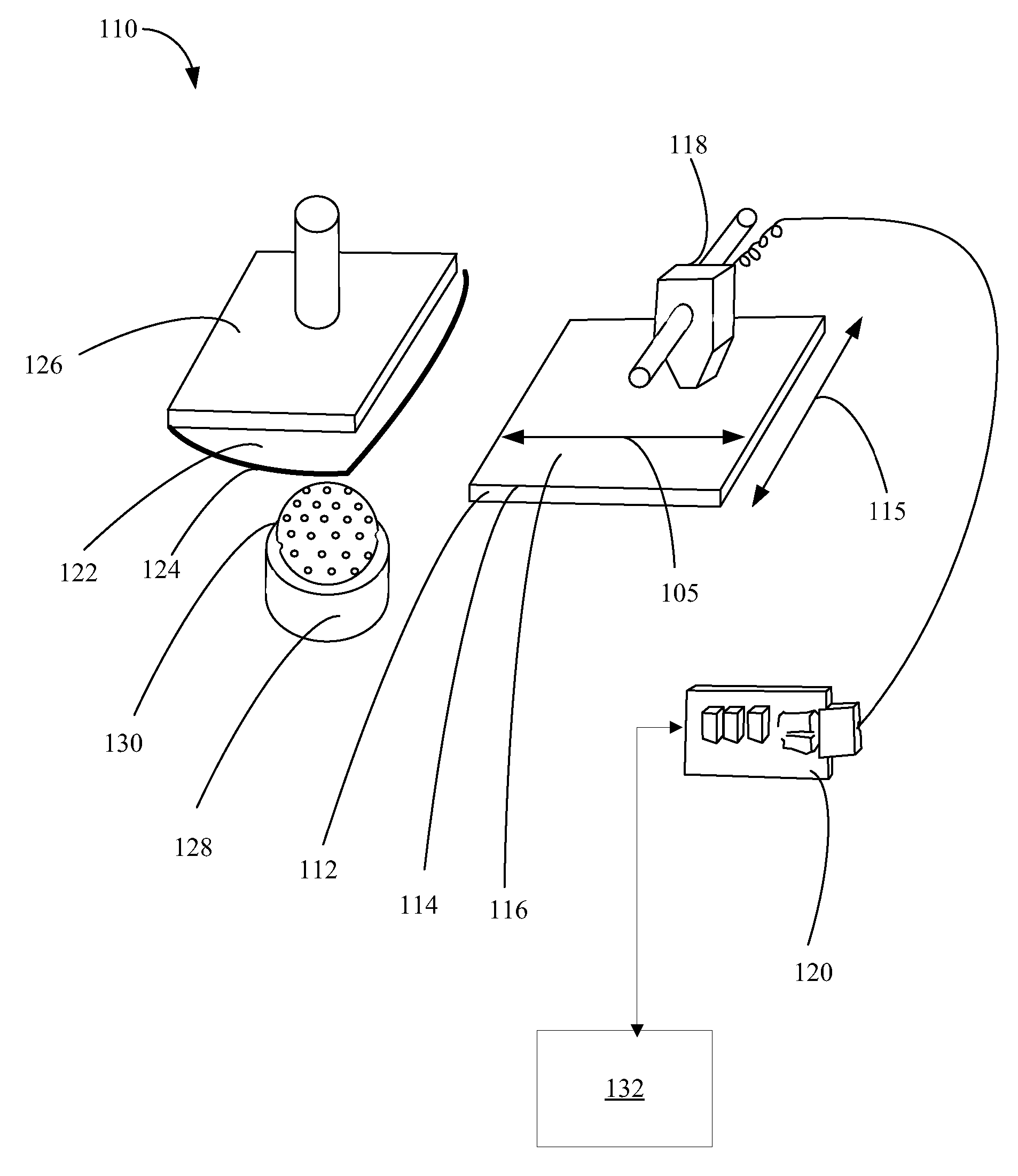
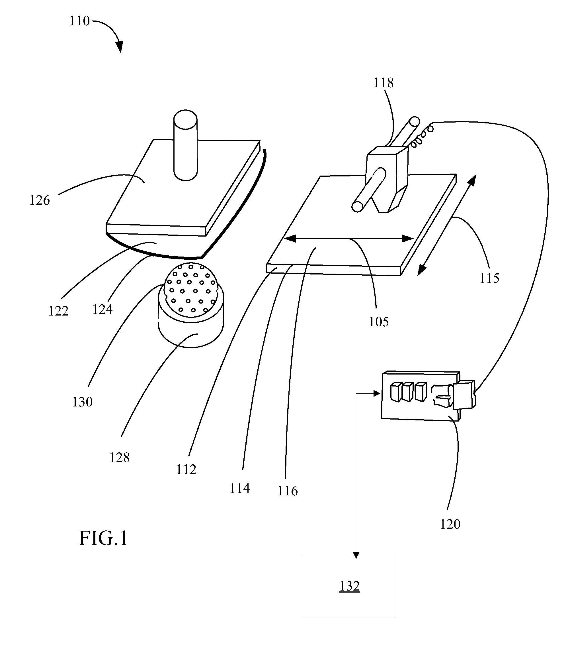
[0015] Referring to FIG. 1, one embodiment of an ink jet pad printing system in accordance with the invention is generally shown at 110.

[0016] The ink jet pad printing system includes a cliché device 112. The ink jet pad printing system forms an image by depositing ink on an imaging surface 114, which is located on an exposed surface of the cliché device 112. An image formed by the ink jet printing system depositing ink on the imaging surface 114 will herein be called an “ink jet deposited image.

[0017] The imaging surface 114 includes at least one etched zone 116 that is configured to hold deposited ink in such manner that ink will remain in position where deposited, and will not run or spread. In one embodiment of the invention the etched zone 116 is created by etching the entire imaging surface 114 to a depth of between 5 microns and 100 microns. In one embodiment, the etched zone 116 includes uniform etching that is not indicative of the ink jet deposited image.

[0018] An ink j...


PUM

PropertyMeasurementUnit
Radiusaaaaaaaaaa

Abstract

A pad printing system has an ink jet printing mechanism, a cliché device including an imaging surface, a pad assembly including a deformable pad, and an ink jet printing controller. The ink jet printing controller controls positioning of the ink jet printing mechanism to deposit a ink jet deposited image on the imaging surface. A method of printing an image on a workpiece surface includes forming an ink jet deposited image on an imaging surface of a cliché device, transferring the ink jet deposited image from the imaging surface to a deformable pad, and transferring the ink jet deposited image from the deformable pad to the workpiece surface.

Description

RELATED APPLICATIONS [0001] This application claims the benefit of U.S. Provisional Patent Application 60 / 754,403 filed Dec. 28, 2005, the entirety of which is incorporated by reference herein.BACKGROUND OF THE INVENTION [0002] The present invention relates to pad printers. More particularly, the present invention relates to a pad printing system. [0003] Pad printing systems are used to apply print, e.g. trademarks and decorations, on non-flat surfaces. For example, pad printing systems can be used to print logos and the like on game balls such as golf balls. Such printing must be carried out on a surface that is not only spherical but is often dimpled as well. [0004] A conventional pad printing system uses a flat cliché plate which has an etching or engraving of a printable image formed thereon. The system transfers ink from an ink supply to the plate, where the ink fills into the etched areas. The system presses a deformable pad onto the cliché plate, and the deformable pad picks ...

Claims


Application Information

Patent Timeline
IPC IPC(8): B41F17/00
CPCA63B45/02B41F17/001B41F17/30B41J2/0057B41J3/4073B41M1/40B41M5/0256B41M5/03
Inventor HITCHCOCK, ROBERT
Owner ILLINOIS TOOL WORKS INC
Why Eureka
Try Eureka