
Systems and methods of electromagnetic influence on electroconducting continuum
a technology of electromagnetic influence and conducting media, applied in the direction of furnaces, heat treatment apparatus, charge manipulation, etc., can solve the problems of increasing the density and hardness of castings, and achieve the effects of high nonlinearity of the electromagnetic response of the medium, rapid and profound homogenization of the temperature of the medium, and advantageous energy efficiency
- Summary
- Abstract
- Description
- Claims
- Application Information
AI Technical Summary
Benefits of technology
Problems solved by technology
Method used
Image

Examples
first embodiment
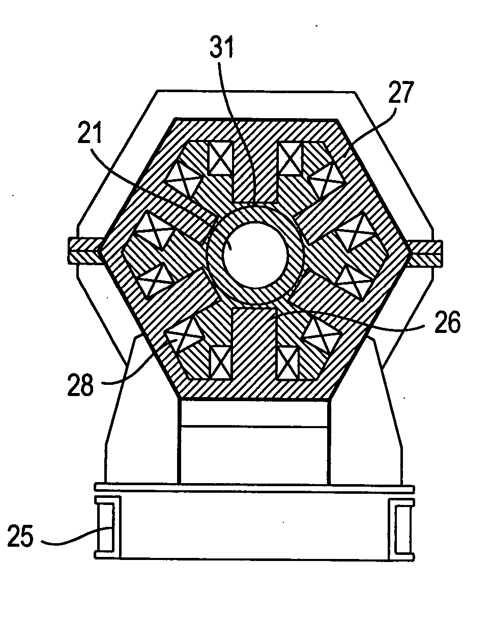
[0084]FIGS. 11 and 12 show vertical and horizontal sections of a furnace of the present invention. The furnace comprises lined shaft 41, channel section 42, furnace transformer 43, primary winding 44 of the transformer, channel 45, and frame 46. Magnetic circuit 47 made of ferroceramic elements is built into the lining of shaft 41. Coils 48, which are made in the form of ceramic boxes with a helical channel (see, e.g., channel 29, FIGS. 9 and 10) are attached on the poles of shaft 41. Channel 29 is filled with liquid metal, whose melting temperature is much lower than the temperature of the melt in the furnace, and whose boiling temperature is much higher than that of the melt (tin can be used as such a metal, for example).
[0085] In the back part of coil 48, which has a comparatively low temperature, solid electrodes 30 in FIG. 9 are introduced, one of which is tubular and another of which is solid, through which an electric current is applied to the liquid-metal winding, and the me...
second embodiment
[0086]FIGS. 13 and 14 show a furnace of the present invention, wherein poles 47c made of ferroceramics with coils 48′ are arranged in the furnace lining, and back 47b of the magnetic circuit of the RMF inductor is made of laminated transformer steel and fixed to the shaft jacket.
[0087]FIG. 15 shows the first embodiment of a furnace of the present invention shown in FIGS. 11 and 12 with an extended shaft and a three-phase inductor. Depending on the alteration of phases in the coils arranged in vertical and horizontal planes, such an inductor can excite a helical magnetic field, RMF, or magnetic field traveling along the furnace axis. At an amplitude and frequency modulation of such fields, both mean velocities of helical, rotary, or vertical flows, respectively, and pulsating velocity components ensuring a forced highly-intense turbulent spectrum of melt oscillations grow considerably (preferably, by at least an order of magnitude). As a result, melting time in furnaces of a sufficie...
PUM
| Property | Measurement | Unit |
|---|---|---|
| temperatures | aaaaa | aaaaa |
| particle size | aaaaa | aaaaa |
| Curie temperature | aaaaa | aaaaa |
Abstract
Description
Claims
Application Information