Dual-band filter

a filter and dual-band technology, applied in the field of filters, can solve problems such as electromagnetic interference (emi)

Active Publication Date: 2007-06-28
CLOUD NETWORK TECH SINGAPORE PTE LTD
View PDF7 Cites 4 Cited by
  • Summary
  • Abstract
  • Description
  • Claims
  • Application Information

AI Technical Summary

Problems solved by technology

Conventionally, electromagnetic signals are generated when a wireless communication product, such as an access point complying with IE

Method used


Image

  • Dual-band filter
  • Dual-band filter
  • Dual-band filter

Examples


Embodiment Construction

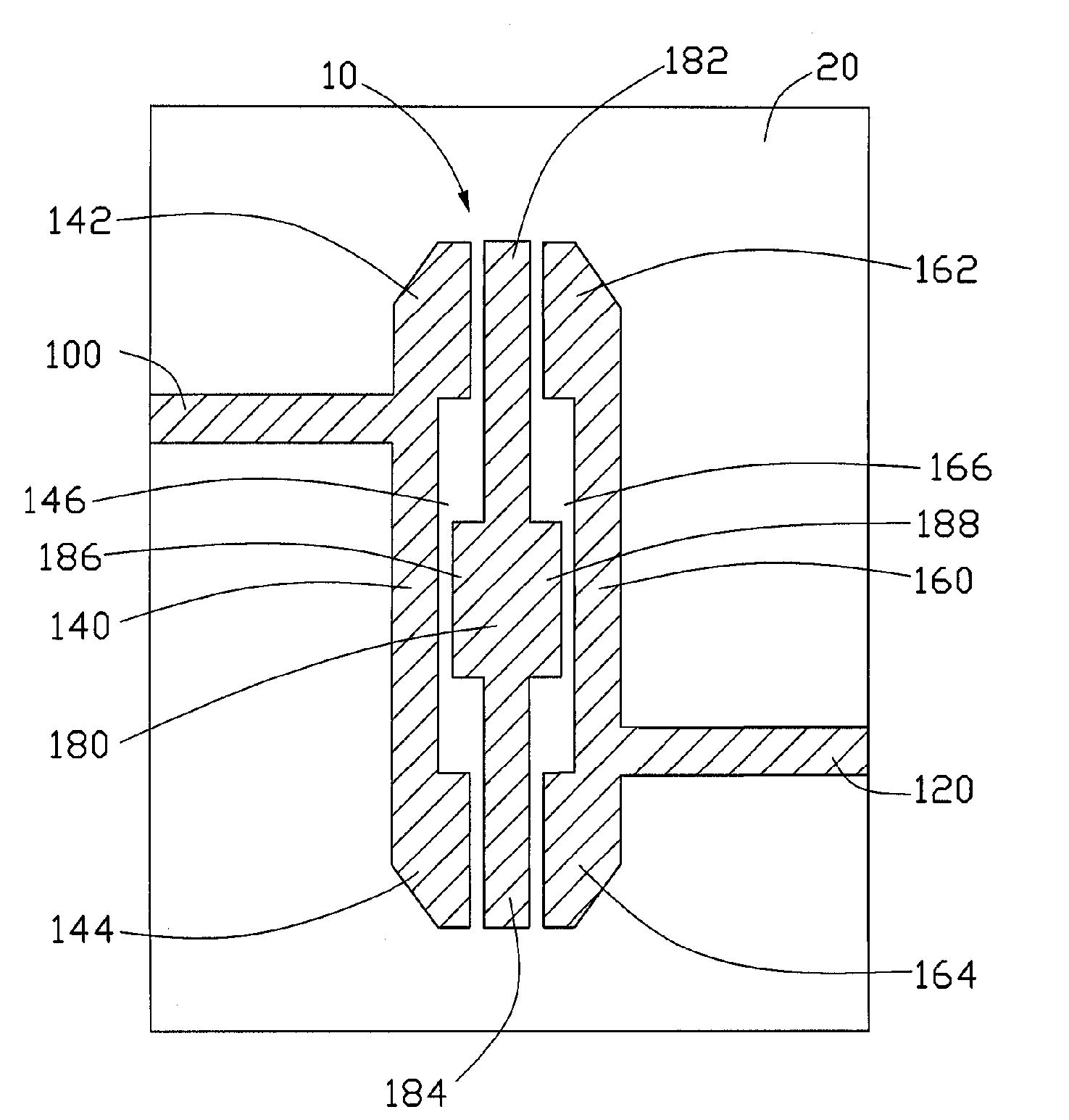
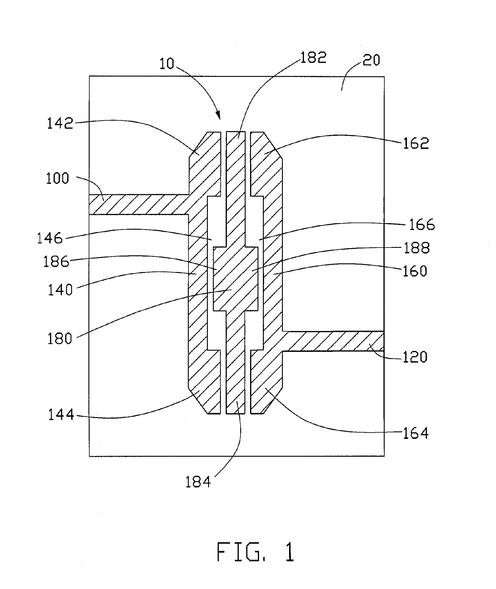
[0010]FIG. 1 is a schematic diagram of an exemplary dual-band filter 10 of the present invention.

[0011]The dual-band filter 10, printed on a substrate 20, is used for cutting out harmonic electromagnetic signals. The dual-band filter 10 includes an input line 100, an output line 120, a first transmission line 140, a second transmission line 160, and a third transmission line 180.

[0012]The input line 100 is used for inputting electromagnetic signals. The output line 120 is used for outputting electromagnetic signals. The output line 120 is arranged parallel to the input line 100, and is electronically connected to the second transmission line 160. Impedances of the input line 100 and the output line 120 are approximately equal to 50 ohms.

[0013]The first transmission line 140 is electronically connected to the input line 100. The first transmission line 140 includes a first free end 142, a second free end 144, and a first recessed portion 146. The first recessed portion 146 is arrange...


PUM


Abstract

A dual-band filter (10) is provided. The dual-band filter includes an input line (100), a first transmission line (140), a second transmission line (160), a third transmission line (180), and an output line (120). The input line is used for inputting electromagnetic signals. The first transmission line is electronically connected to the input line. The second transmission line is arranged parallel to the first transmission line. The third transmission line is arranged between, and parallel to, the first transmission line and the second transmission line. The output line for outputting electromagnetic signals, is arranged parallel to the input line, and is electronically connected to the second transmission line.

Description

1. FIELD OF THE INVENTION[0001]The present invention generally relates to filters, and more particularly to a dual-band filter.2. DESCRIPTION OF RELATED ART[0002]In recent years, there has been a significant growth in WLAN (wireless local area network) technology due to the increasing demand of wireless communication products. Such growth becomes particularly prominent after promulgation of an IEEE 802.11 WLAN protocol in 1997. The IEEE 802.11 WLAN protocol not only offers many novel features to current wireless communications, but also provides a solution of enabling two wireless communication products manufactured by different companies to communicate with each other. As such, the promulgation of the IEEE 802.11 WLAN protocol is a milestone in the development of WLAN. Moreover, the IEEE 802.11 WLAN protocol ensures that a core device is the only solution of implementing a single chip. Thus, the IEEE 802.11 WLAN protocol can significantly reduce the cost of adopting wireless techno...

Claims


Application Information

Patent Timeline
IPC IPC(8): H01P1/203
CPCH01P1/20381
Inventor SHIH, YEN-YI
Owner CLOUD NETWORK TECH SINGAPORE PTE LTD
Why Eureka
Try Eureka