Method and an apparatus for the continous mixing of two flows

a technology of continous mixing and flow, applied in the directions of mixing, emulsification, transportation and packaging, etc., can solve the problems of increasing raw material costs, and occupying considerable spa

Inactive Publication Date: 2007-07-05
TETRA LAVAL HLDG & FINANCE SA
View PDF8 Cites 194 Cited by
  • Summary
  • Abstract
  • Description
  • Claims
  • Application Information

AI Technical Summary

Benefits of technology

[0007] One object of the present invention is to realise a method and an apparatus where it is possibl

Problems solved by technology

If there is an insufficient mixture and, as a result, an unreliable Brix value in the subsequent measurement, it must be ensured that there is a margin to the lowest permitted Brix value, which involves increased raw materials costs.
This method is both costly and takes up considerable space.
These give rise to turbulence in the flows, which results in a mixture of the differ

Method used


Image

  • Method and an apparatus for the continous mixing of two flows
  • Method and an apparatus for the continous mixing of two flows

Examples


Embodiment Construction

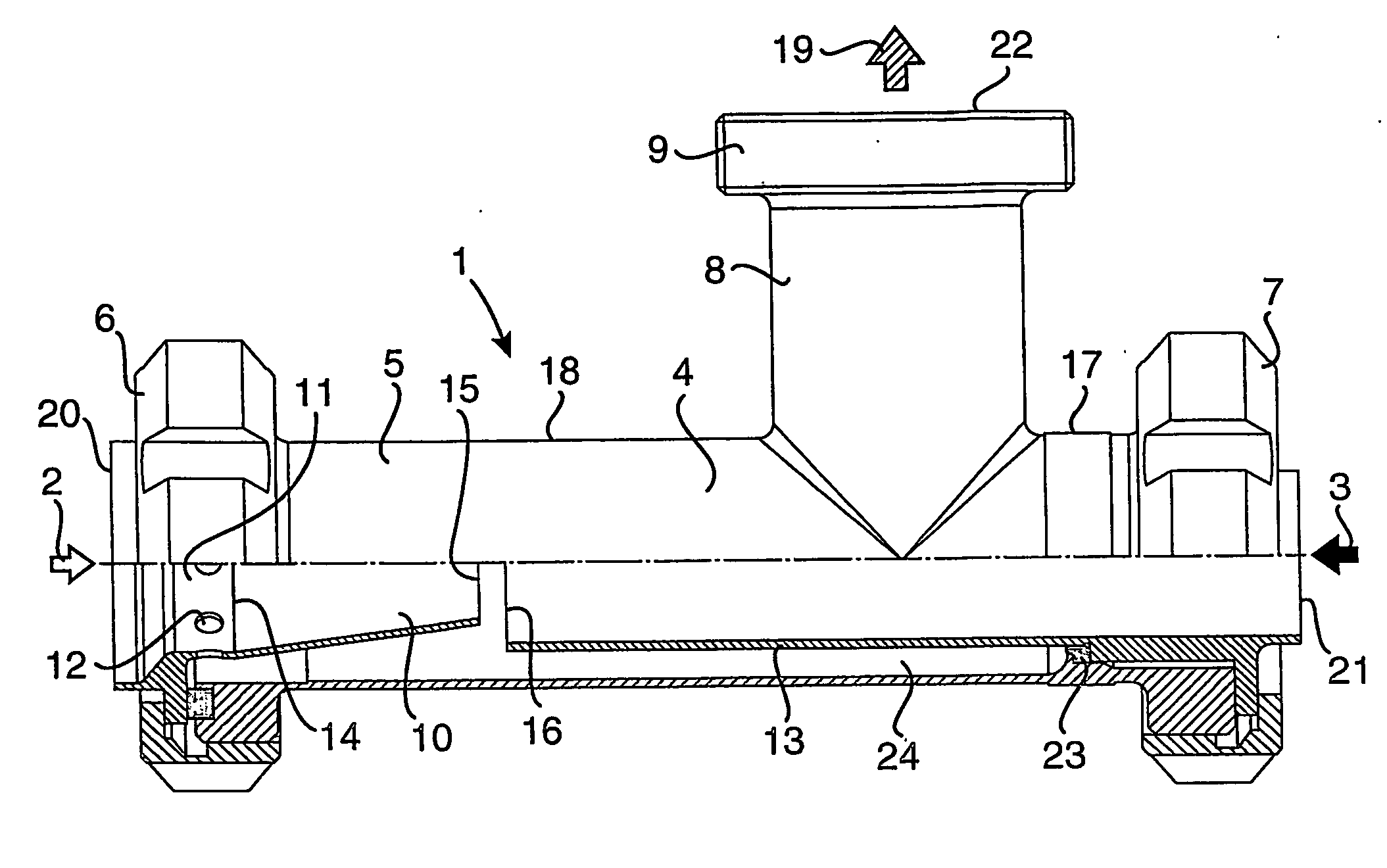
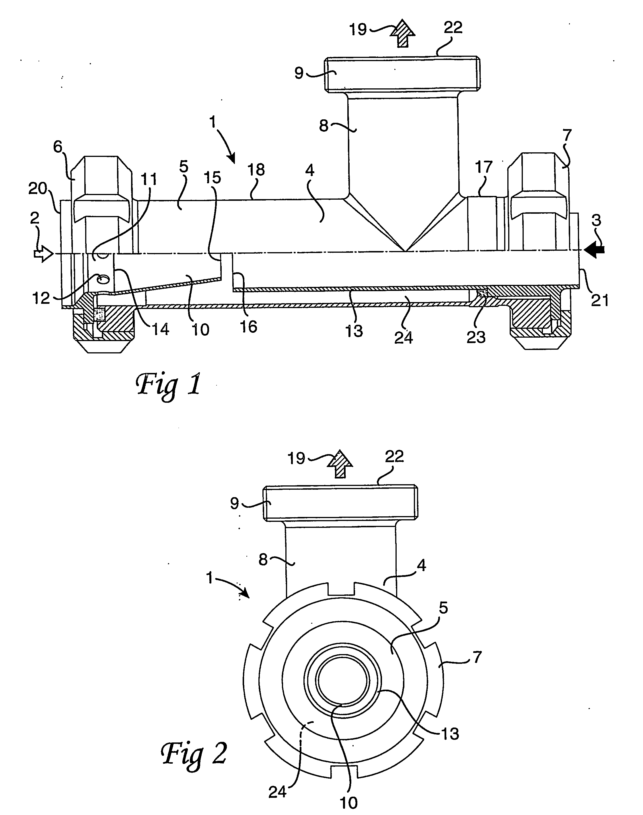
[0016] The accompanying Drawings show an apparatus 1 which may be employed for mixing two flow, a first, larger flow 2 and a second, smaller flow 3. The first flow 2 may, for example, consist of water and the second flow 3 may be a fruit juice with or without fibres. The flows 2, 3 are shown in FIG. 1 by means of arrows.

[0017] The apparatus 1 includes a T pipe 4 which is placed at that point in a plant where the intention is to mix two flows. The T pipe 4 may consist of a standard T pipe which is modified in order to be able to be employed as a mixer. Such a T pipe 4 may, in principle, be described as consisting of a pipe length 5 with a connection in each end, a first connection 6 and a second connection 7. The first connection 6 and the second connection 7 are thus disposed at 180° in relation to one another. On the pipe length 5, an additional pipe length 8 is fixedly welded at 90° in relation to the first pipe length 5. The fixedly welded pipe length 8 also has, in its end, a c...


PUM

PropertyMeasurementUnit
Fractionaaaaaaaaaa
Angleaaaaaaaaaa
Angleaaaaaaaaaa

Abstract

The disclosure relates to a method and an apparatus (1) for continuously mixing two flows, a first, larger flow (2) and a second, smaller flow (3). The second flow (3) is introduced counter-directed into the first flow (2). The apparatus (1) comprises a T pipe (4) where a first connection (6) constitutes an inlet (20) for the first flow. A second connection (7), at 180° in relation to the first connection (6), constitutes an inlet (21) for the second flow (3). The second flow (3) is led into the first flow (2) through a conduit (13) within the T pipe (4). The first connection (6) is provided with a conical portion (10) in which are provided a number of holes (12), so that the first flow (2) is throttled and divided up into a plurality of subflows immediately before the mixing operation. A third connection (9) is oriented at 90° in relation to the other connections (6, 7) and constitutes an outlet (22) for the intermixed flows (19), which implies that the intermixed flows (19) are caused to change direction immediately after the mixing.

Description

TECHNICAL FIELD [0001] The present invention relates to a method for continuously mixing two flows which consist of a first, larger flow and a second, smaller flow, where the second flow is introduced into the first flow in a direction opposite to that of the first flow, and the mixed flows are caused to change flow direction immediately after the mixing. [0002] The present invention also relates to an apparatus for continuously mixing two flows, the flows consisting of a first, larger flow and a second, smaller flow, and the apparatus comprising a T pipe where a first connection constitutes an inlet for the first flow and a second connection, at 180° in relation to the first, constitutes an inlet for the second flow, the second flow being led into the first flow through a conduit within the T pipe, and a third connection, at 90° in relation to the two other connections, constituting an outlet for the mixed flows. BACKGROUND ART [0003] In the production of drinks, such as fruit juic...

Claims


Application Information

Patent Timeline
IPC IPC(8): B01F15/06B01F3/08B01F5/02
CPCB01F3/08B01F3/0865B01F2215/0431B01F2215/0022B01F5/0256B01F23/40B01F23/451B01F25/23B01F2101/14
Inventor LUNDGREN, ERICPALM, BENGT
Owner TETRA LAVAL HLDG & FINANCE SA
Why Eureka
Try Eureka