Smart antenna beamforming device in communication system and method thereof

a technology of communication system and beamforming device, which is applied in the direction of multi-channel direction-finding system using radio waves, baseband system details, instruments, etc., can solve the problems of difficult to regenerate information of desired signals, difficult to separate doas from various paths, communication distortion may be caused, etc., to maximize the signal-to-interference ratio

Active Publication Date: 2007-07-19
SAMSUNG ELECTRONICS CO LTD +4
View PDF4 Cites 96 Cited by
  • Summary
  • Abstract
  • Description
  • Claims
  • Application Information

AI Technical Summary

Benefits of technology

[0012] The present invention provides a smart antenna beamforming device for forming a beamforming vector for maximizing a signal to interference ratio by using an adaptive array antenna in a base station, and a method thereof.

Problems solved by technology

Accordingly, when the level of the desired signal is much greater than the levels of the respective interference signals and the number of the interference signals is great, communication distortion may be caused since the power levels of the interference signals are increased.
Accordingly, it is difficult to regenerate information of the desired signal due to the communication distortion.
However, in the above method, since a Direction Of Arrival (DOA) of a signal is estimated after the respective antenna elements perform coherent demodulation, when the base station receives the desired signal from various angles due to neighboring obstacles, it is difficult to separate the DOAs from various paths, and angular diversity may not be obtained.
In addition, it is difficult to identify the desired signal and the interference signal by the base station, and it is difficult to combine the signals received from the various angles.
However, in the above method, since the reference signal is transmitted in every subcarrier, it takes a long time to estimate a covariance matrix of the received signal.

Method used


Image

  • Smart antenna beamforming device in communication system and method thereof
  • Smart antenna beamforming device in communication system and method thereof
  • Smart antenna beamforming device in communication system and method thereof

Examples


Embodiment Construction

[0023] Preferred embodiments of the present invention will be described herein below with reference to the accompanying drawings. In the following description, well-known functions or constructions are not described in detail since they would obscure the invention in unnecessary detail. As those skilled in the art would realize, the described embodiments may be modified in various different ways, all without departing from the spirit or scope of the present invention. Accordingly, the drawings and description are to be regarded as illustrative in nature and not restrictive. Like reference numerals designate like elements throughout the specification.

[0024] Unless explicitly described to the contrary, the word “comprise” and variations such as “comprises” or “comprising” will be understood to imply the inclusion of stated elements but not the exclusion of any other elements.

[0025] A smart antenna scheme is classified into a plurality of schemes according to beamforming methods. A s...


PUM


Abstract

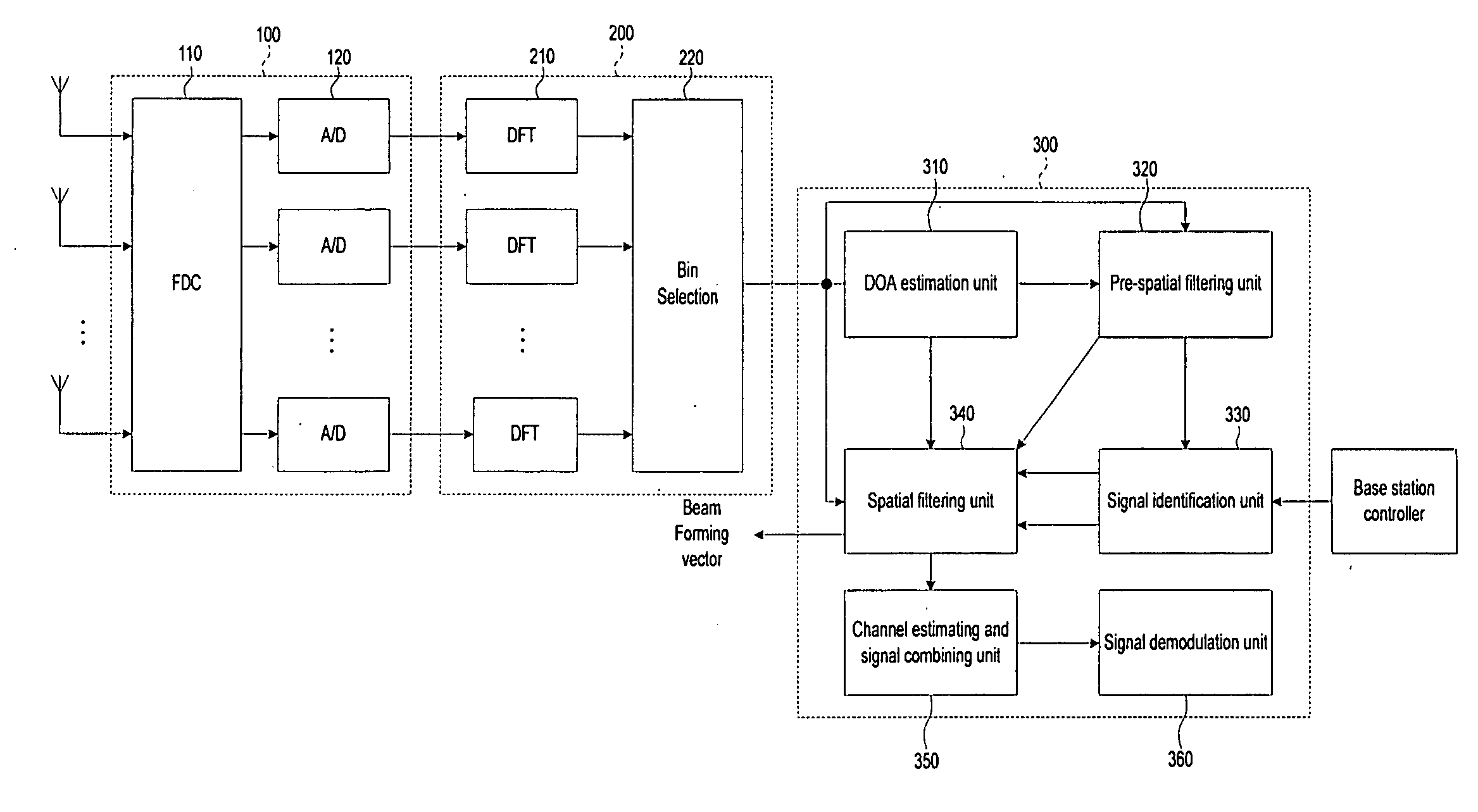
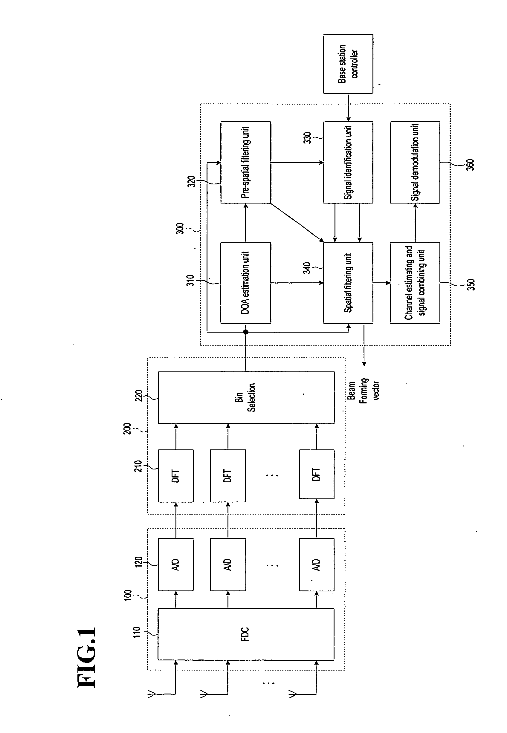
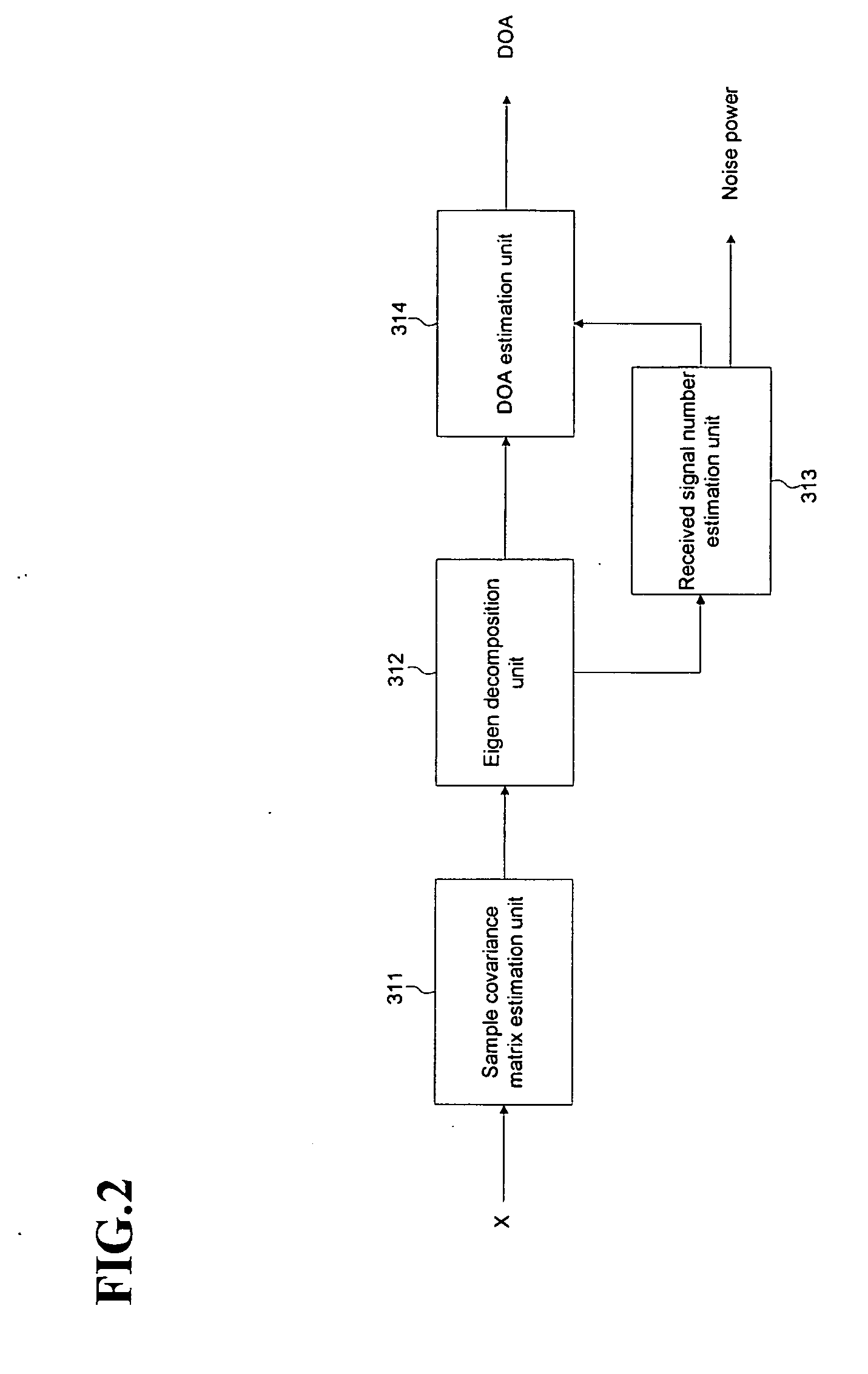
A beamforming device includes a Direction Of Arrival (DOA) estimation unit for estimating DOAs of the received signals based on a data subcarrier matrix; a pre-spatial filtering unit for using the estimated DOA, performing a filtering operation for the data subcarrier matrix, and generating filtering matrixes; a signal identification unit for using a data sequence, identifying original and interference signals, and generating the DOAs of the original and interference signals; a spatial filtering unit for generating an interference-plus-noise covariance matrix by using the DOA of the interference signal, eliminating the interference signal by using the covariance matrix and the DOA of the original signal, and forming final beams for the original signal; and a channel estimating and signal combining unit for performing a maximal ratio combining operation so that the final beams are combined as one combined final beam.

Description

PRIORITY [0001] This application claims priority under 35 U.S.C. § 119 to Korean Patent Application No. 10-2005-0116882 filed in the Korean Intellectual Property Office on Dec. 2, 2005, the contents of which are incorporated herein by reference. BACKGROUND OF THE INVENTION [0002] 1. Field of the Invention [0003] The present invention generally relates to a beamforming device for increasing a signal to interference ratio by using a direction-of-arrival estimation-based smart antenna process, and a method thereof. [0004] 2. Description of the Related Art [0005] In general, in a mobile communication environment, a desired signal and an unwanted interference signal are received. A communication distortion rate by the interference signal is determined by a sum of a power level of the desired signal and power levels of other signals. Accordingly, when the level of the desired signal is much greater than the levels of the respective interference signals and the number of the interference s...

Claims


Application Information

Patent Timeline
Patent Type & Authority Applications(United States)
IPC IPC(8): H01Q3/00G01S3/16
CPCH04B7/086G01S3/74H04B7/0897H04B7/0857H04L25/0242H04L25/0204H04L27/2691
Inventor BANG, YOUNG-JOYUN, YOUNG-HOYU, CHANG-WAHNPARK, HYUNG RAEPARK, YOUN-OK
Owner SAMSUNG ELECTRONICS CO LTD
Why Eureka
Try Eureka