Slide switch

a technology of sliding switch and sliding plate, which is applied in the direction of electrical equipment, building parts, construction, etc., can solve the problems of weakening the sense of operation, and achieve the effect of smooth operation

Inactive Publication Date: 2007-07-26
HOSIDEN CORP
View PDF10 Cites 5 Cited by
  • Summary
  • Abstract
  • Description
  • Claims
  • Application Information

AI Technical Summary

Benefits of technology

[0010]The object of the present invention is to provide a slide switch with a rational construction capable of realizing a smooth operation when the control member is pressed while being slid.
[0012]In a sliding operation using the control member, the control member is slid with the sliding surface of the control member contacting the support member to exert a pressing force from the control member on any one of the plurality of transverse contacts. The transverse contact contacts the vertical contact thereby to electrically detect the direction of the sliding operation. When the control member is pressed while being slid, a pressing force acts on a position offset from the central portion of the casing. At that time, the posture maintaining mechanism maintains the position, relative to the casing, of the support member contacting the control member. Thus, an inclination of the support member is restrained, and the support member and control member make a parallel movement in the pressing direction. As a result, a smooth operation is realized even when the control member is pressed while being slid.

Problems solved by technology

The control member is inclined by the force unevenly applied to the control member to vary the stroke of the pressing operation and weaken the sense of operation.
Further, the inclination of the control member causes malfunction.

Method used


Image

  • Slide switch
  • Slide switch
  • Slide switch

Examples


Embodiment Construction

[0033]Embodiments of the present invention will be described hereinafter with reference to the accompanying drawings.

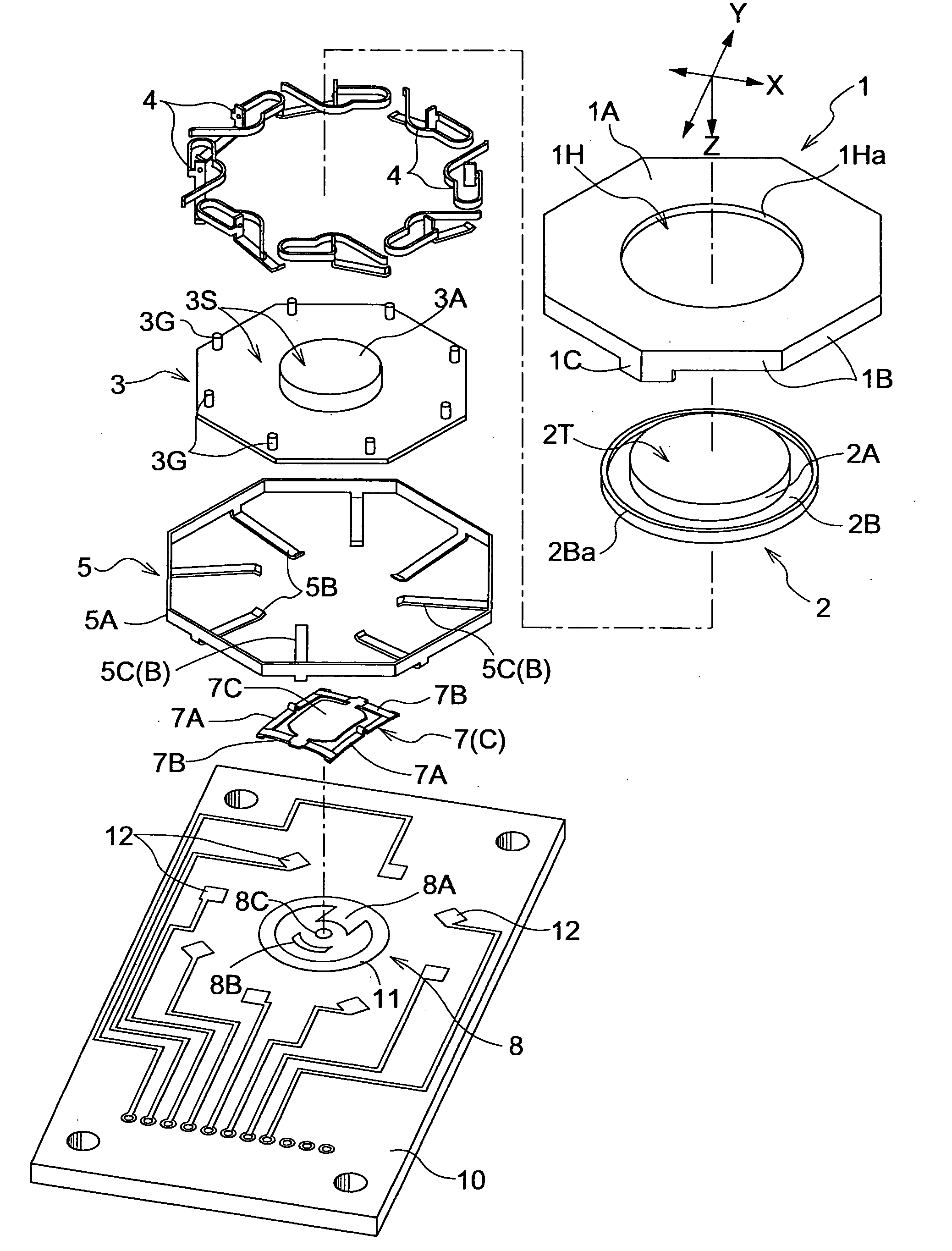
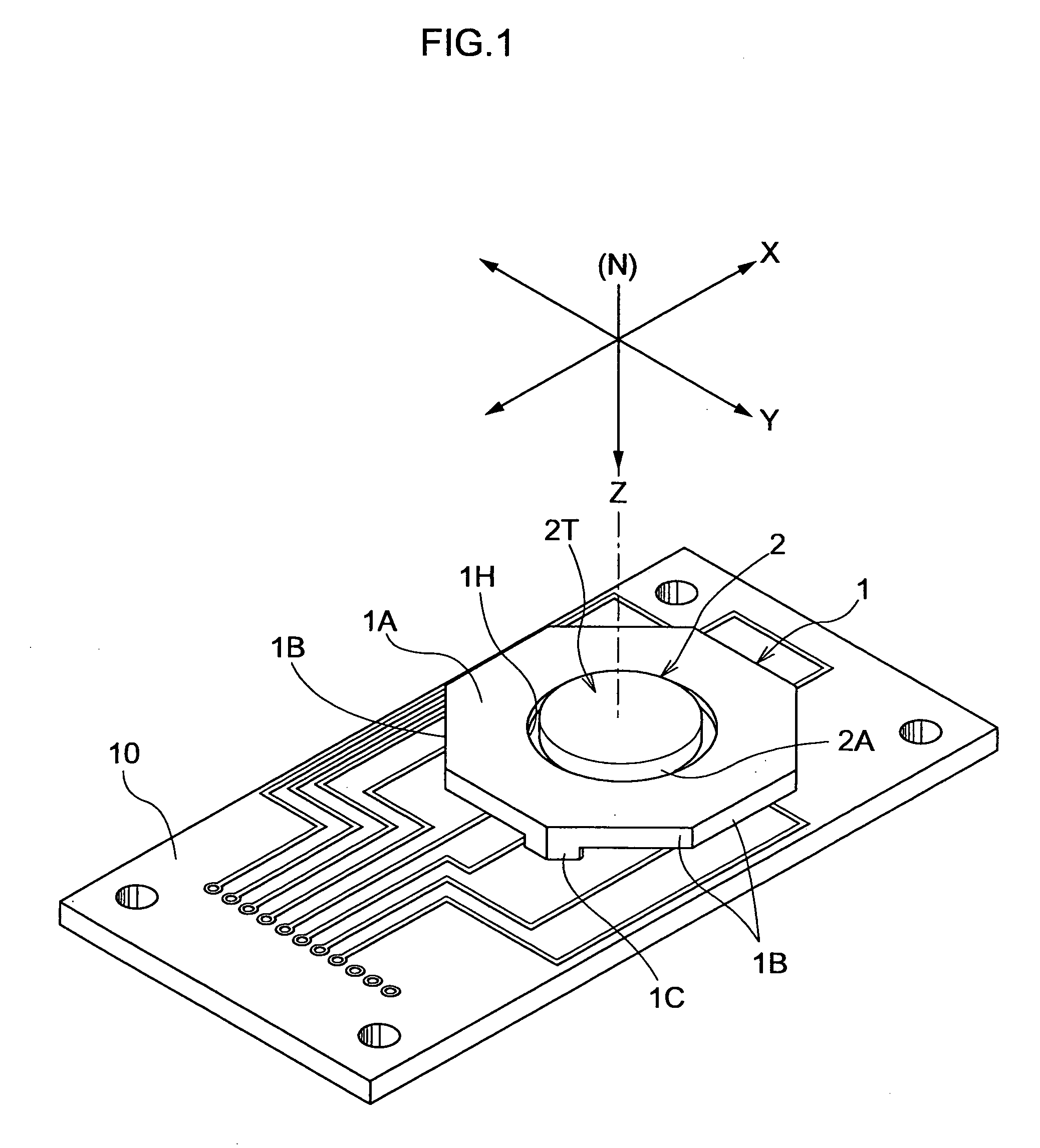
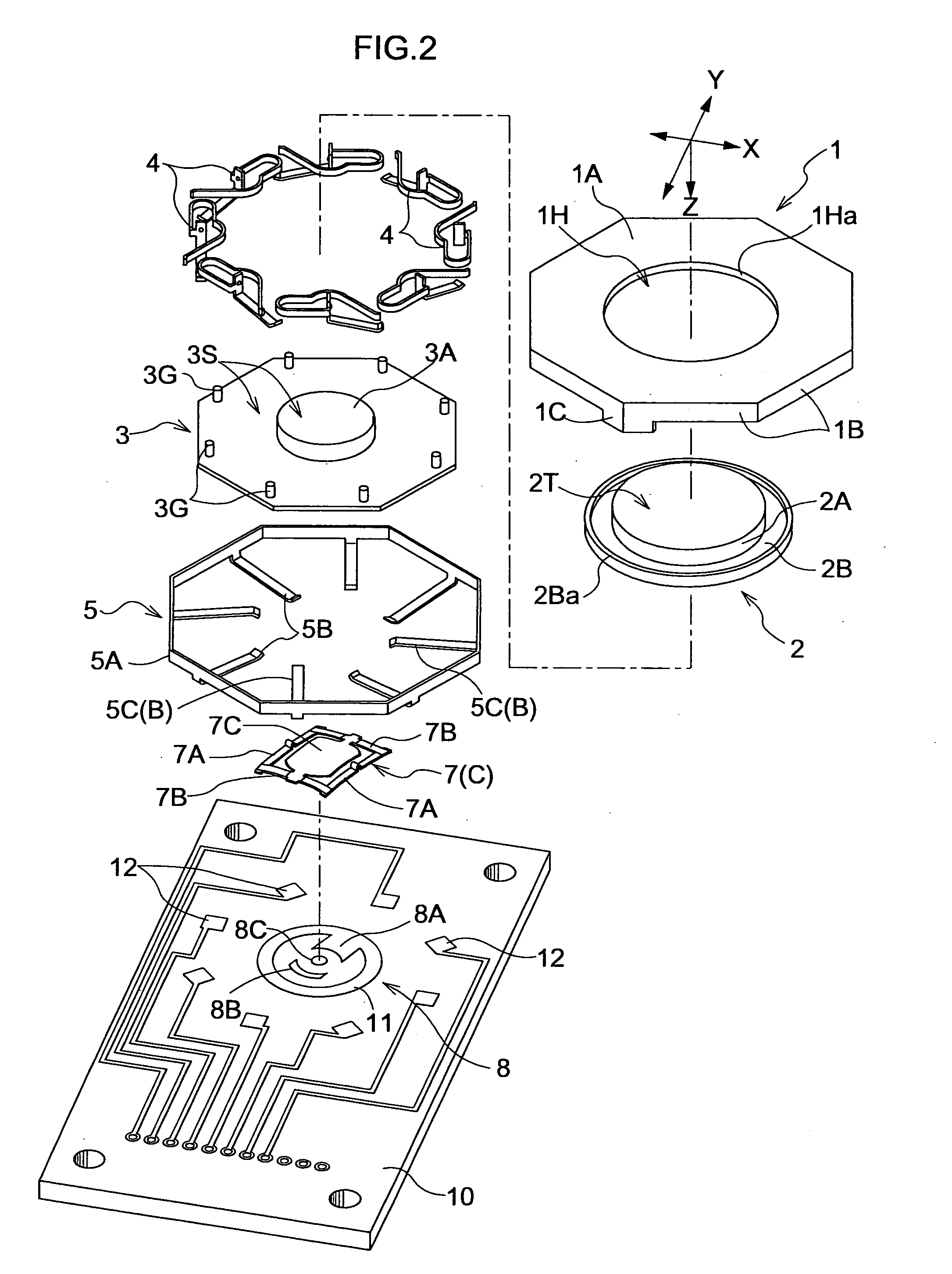
[0034]As shown in FIGS. 1 to 4, a slide switch comprises a regular octagonal casing 1 having a circular opening 1H formed in a central portion thereof to vertically extend therethrough, a disk-shaped control member 2 accommodated in the casing 1, a plate-shaped regular octagonal support member 3 accommodated in the casing 1 as placed in contact with the control member 2, eight transverse contacts 4 supported by the casing 1 in positions to surround the control member 2, a vertical contact 5 in the form of an annular element disposed in a position to surround the eight transverse contacts 4, a posture maintaining mechanism A for realizing a vertical parallel movement of the control member 2 and support member 3 laid one over the other when the control member 2 is pressed, a biasing mechanism B for exerting a biasing force in a direction to push back the support member ...


PUM


Abstract

A slide switch includes a disk-shaped control member laid over a support member accommodated in a casing, a plurality of transverse contacts arranged in positions to surround the control member, and an annular vertical contact arranged outwardly of the transverse contacts to detect a sliding operation of the control member. Rod-shaped guide elements formed on peripheries of the support member are fitted into concaved engageable portions formed in the casing to be relatively movable in the pressing direction when the control member is pressed. The engageable portions and the guide elements constitute a posture maintaining mechanism.

Description

BACKGROUND OF THE INVENTION [0001]1. Field of the Invention[0002]The present invention relates to a slide switch comprising a control member slidable along an imaginary plane and pressable in a direction perpendicular to the imaginary plane, a plurality of transverse contacts arranged to surround the control member, and a vertical contact having a plurality of electrode portions associated with the plurality of transverse contacts to be conductive with any one of the transverse contacts when the control member is slid.[0003]2. Description of the Related Art[0004]Japanese Patent Application “Kokai” No. 2003-31076 (paragraphs [0022] to [0038], and FIGS. 2 to 6) discloses a slide switch including an biasing member formed of elastomer, having four projections, and mounted in a casing, a sliding member fitted into a central portion of the biasing member, and a keytop connected to the sliding member. In this slide switch, four conductive elements are provided on outer peripheries of the b...

Claims


Application Information

Patent Timeline
Patent Type & Authority Applications(United States)
IPC IPC(8): H01H13/70
CPCH01H2025/004H01H25/002E04G17/065E04G17/047
Inventor KONDO, HAYATONAGATA, TAKAYUKI
Owner HOSIDEN CORP
Why Eureka
Try Eureka