
Heat exchanger seal

Inactive Publication Date: 2007-07-26
EI DU PONT DE NEMOURS & CO
View PDF14 Cites 9 Cited by
  • Summary
  • Abstract
  • Description
  • Claims
  • Application Information

AI Technical Summary

Benefits of technology

[0050] It is therefore apparent that there has been provided in accordance with the present invention, an improved heat exchanger seal that fully satisfies the aims and advantages hereinbefore set forth. While this invention has been described in conjunction with a specific embodiment thereof, it is evident that many alternatives, modifications, and variations will be apparent to those skilled in the art. Accordingly, it is intended to embrace all such alternatives, modifications and variations that fall within the spirit and broad scope of the appended claims.

Problems solved by technology

During the operation of the system, heat transfer would occur between the first and second fluids since in many applications, it would be disadvantageous to have the material on the inside of the tubes commingle with the material on the exterior.
Although each design accomplishes the goal of relieving thermal stress on the exchanger, each configuration has a different set of drawbacks.
The disadvantage with this design is that many tubes must be omitted from the edge of the bundle to allow for the bonnet flange and bolt circle.
Each of these suffers primarily from the disadvantage that they are difficult to seal and are prone to leakage at the tube bundle to shell joint.

Method used


Image

  • Heat exchanger seal
  • Heat exchanger seal
  • Heat exchanger seal

Examples


Embodiment Construction

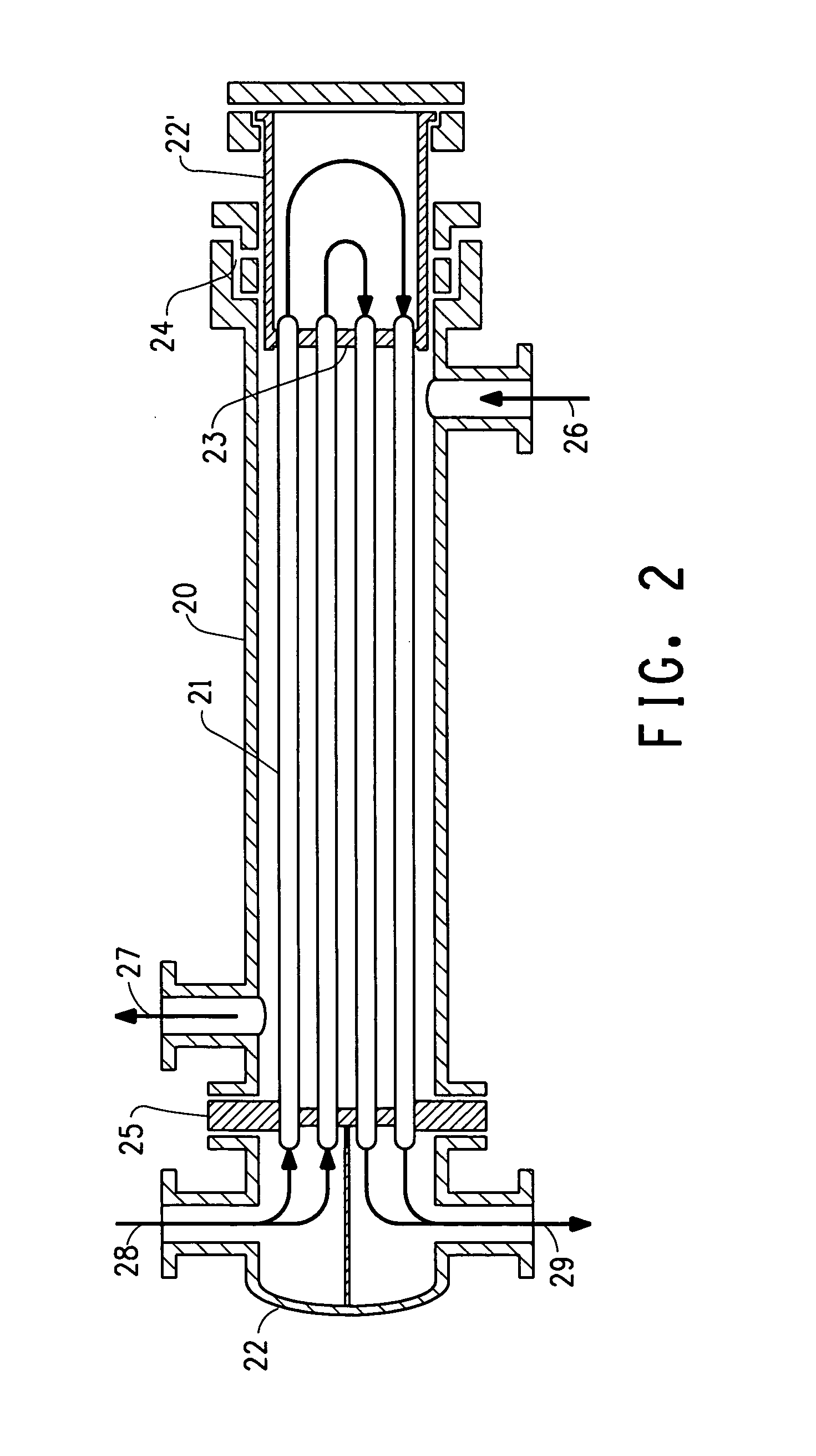
[0039] The seal assembly of the invention can be used to seal between any two metal surfaces in which it is required to allow relative motion between the two surfaces during thermal cycling. An embodiment of the invention is suitable for use as a seal assembly in a floating head heat exchanger. The invention can best be understood by reference to the Figures.

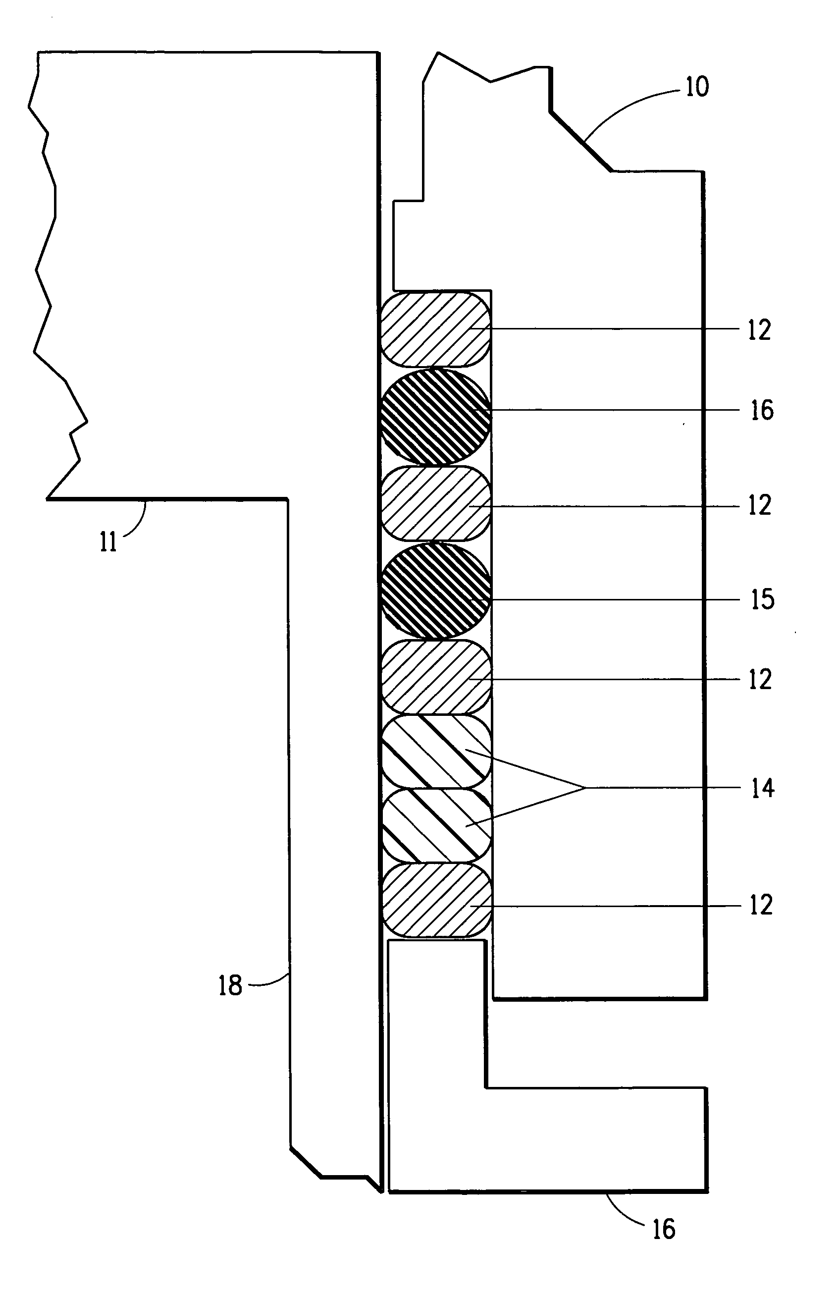
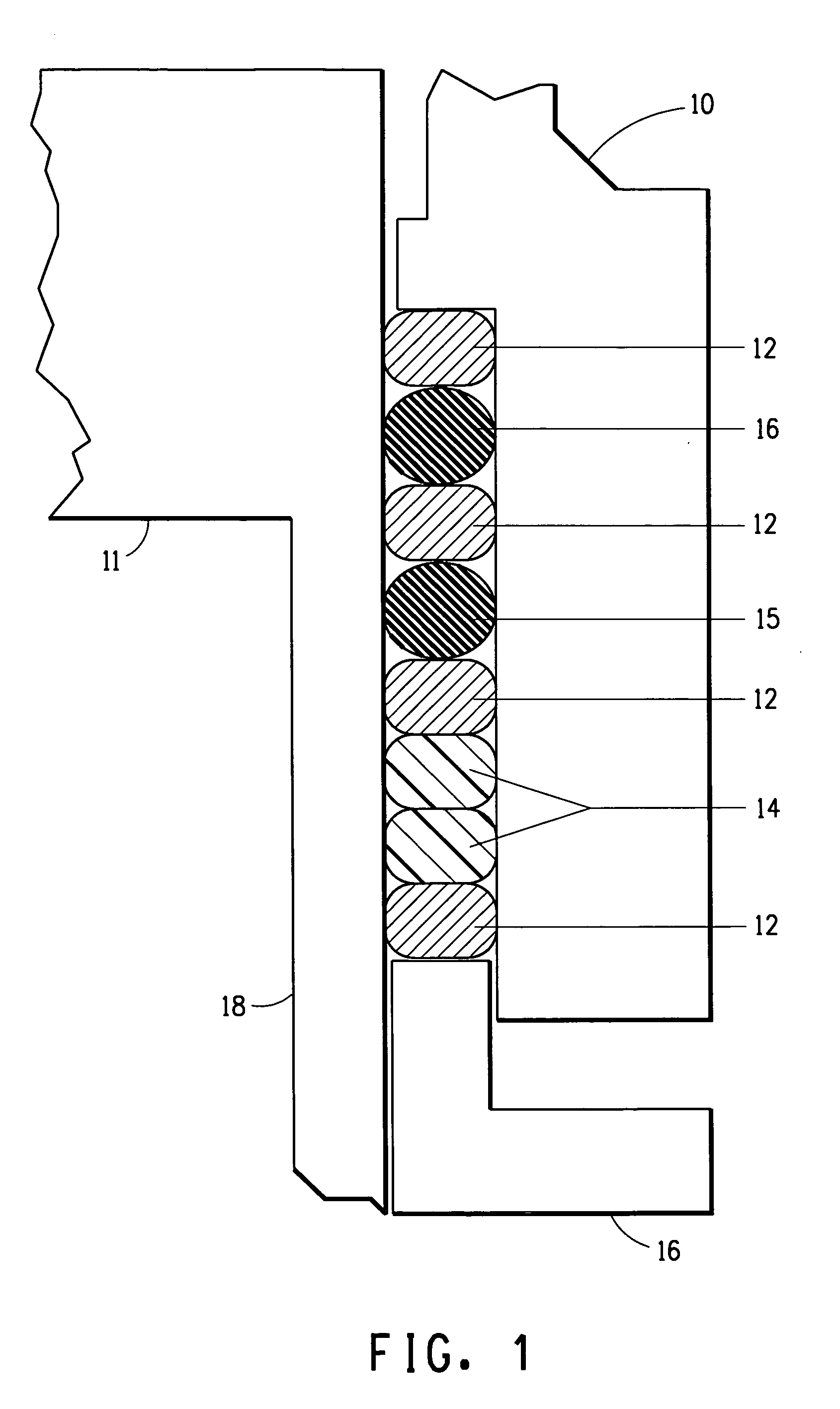
[0040]FIG. 1 shows an example of an embodiment of the seal assembly of the invention. The sealing system comprises the shell or other wall of the heat exchanger (10) which is required to be sealed against a tubesheet (11) which may have a skirt (18). The seal assembly (12-15) comprises non-extrudable packing layers (12) that can act as load distribution layers. At least one non-extrudable packing layer is disposed at each end of the seal assembly.

[0041] An example of a non-extrudable packing layer would be copper wire braided packing available from ChemStar Packing (Mulberry, Fla.) such as “style 49”. Any packing material can ...


PUM


Abstract

A seal for use between two metal surfaces and allowing relative motion between the two surfaces during thermal cycling. The seal comprises a non-extrudable packing layer adjacent to a first end of the seal assembly. The seal further comprises one or more elastomeric O-rings, one or more load distribution packing layers, one or more braided plastic packing layers having elastomeric cores, with a non extrudable packing layer adjacent to a braided plastic packing layer and disposed at a second end of the seal and, optional additional non extrudable packing layers.

Description

[0001] This application claims the benefit of U.S. Application No. 60 / 741,164, filed Dec. 1, 2005.FIELD OF THE INVENTION [0002] The present invention relates to shell and tube type heat exchangers and more particularly to packing methods for floating tube sheet type exchangers. BACKGROUND OF THE INVENTION [0003] A conventional shell and tube type heat exchanger comprises generally a tubular shell or casing having a pair of inlet / outlet pipes through which a first fluid is passed, and a tubestack received within the casing. The tubestack is composed of generally parallel tube elements through which a second fluid is passed for heat exchange with the above-mentioned first fluid, the tube elements extending between and being supported by a pair of support members or tube plates. The tubestack also includes a plurality of baffles disposed between the tube plates and extending transversely to the tube elements. [0004] The second fluid is supplied to the tubestack by means of inlet / outlet...

Claims


Application Information

Patent Timeline
IPC IPC(8): F02F11/00
CPCF28D7/1638F28F9/0219F28F2230/00F28F9/0241F28F9/0239F28F9/02F16J15/18
Inventor BURGESS, MICHAELHOUCK, THOMAS
Owner EI DU PONT DE NEMOURS & CO
Features
  • Generate Ideas
  • Intellectual Property
  • Life Sciences
  • Materials
  • Tech Scout
  • Unparalleled Data Quality
  • Higher Quality Content
  • 60% Fewer Hallucinations
Learn More