Storage and ink refilling station for a cartridge or a printhead

a technology of ink refilling station and cartridge, which is applied in the direction of brushes, coatings, laboratory glassware, etc., can solve the problems of ink flowing out of the cartridge and overfilling of the cartridg

Inactive Publication Date: 2007-07-26
TELECOM ITALIA SPA
View PDF6 Cites 13 Cited by
  • Summary
  • Abstract
  • Description
  • Claims
  • Application Information

AI Technical Summary

Benefits of technology

[0005] Another object of this invention is to produce a perfected storing and ink refilling station, in which the cartridge is refilled with ink when the station is in the vertical position, while refilling with ink is interrupted when the storage station is in any other position other than the vertical, in this way avoiding ink dripping or running through the capillary element.

Problems solved by technology

This device has the drawback that when the container is turned over on a side or turned upside down, during transport for instance, the capillary element remains in contact with the ink and continues transferring the ink to the cartridge not only through capillarity but also on account of the head of ink above the capillary element, therefore causing an overfilling of the cartridge with, as a result, ink flowing out of the cartridge.
This drawback is most apparent in cases where the cartridge is not in the first chamber, in which case, ink would drip in abundance inside the first chamber.

Method used


Image

  • Storage and ink refilling station for a cartridge or a printhead
  • Storage and ink refilling station for a cartridge or a printhead
  • Storage and ink refilling station for a cartridge or a printhead

Examples


Embodiment Construction

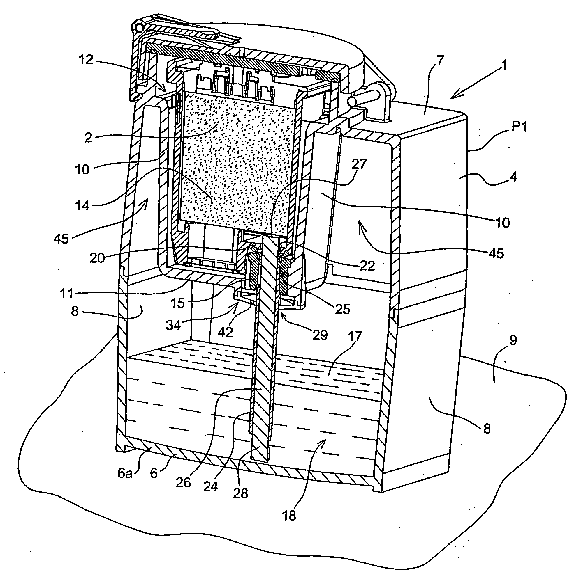
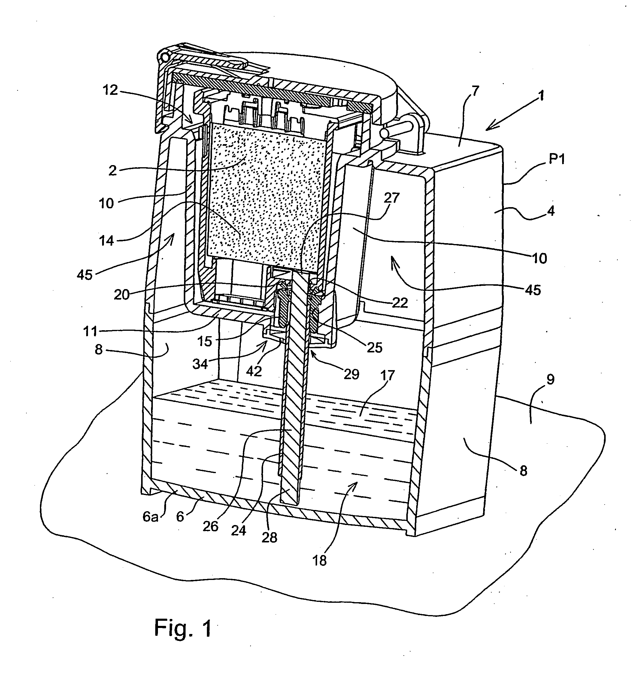
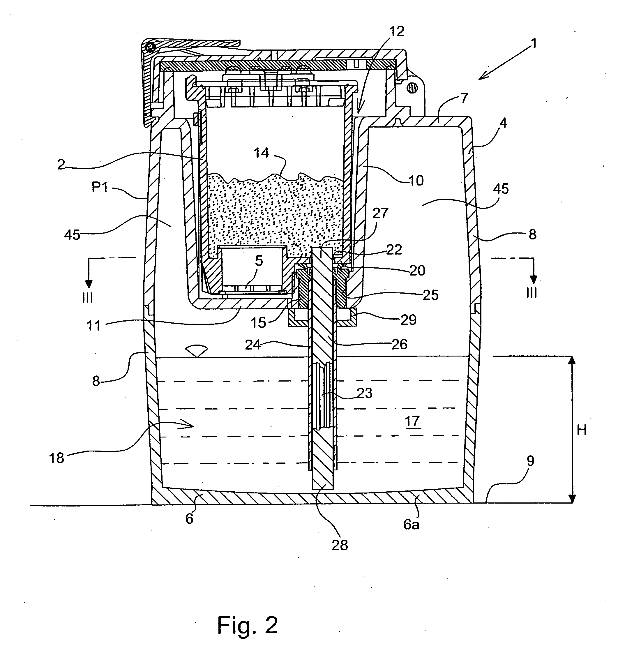
[0013] The station 1, in accordance with the present invention, for storing and refilling a cartridge 2 of a printhead, depicted in FIG. 1, comprises a container 4 consisting of a bottom wall 6, a top wall 7, substantially parallel to the bottom wall 6, and at least one side wall 8, integrally attached to the other two walls 6 and 7.

[0014] The bottom wall 6 acts as the support platform of the container 4 on a horizontal plane 9, for setting the container in a vertical operating position P1, in order to refill the cartridge 2 with ink, as will be described in greater detail in the following.

[0015] The container 4 can indifferently be made in a cylindrical shape, or as a parallelepiped, or a right-angled prism; in the first case, the side wall 8 will be made in a single, continuous piece, substantially shaped as a cylinder trunk; in the second case the side wall 8 will be made of various flat walls, four for instance, 8a, 8b, 8c and 8d, joined together and to the walls 6 and 7.

[001...


PUM


Abstract

A station for storing and refilling a cartridge of a printhead has a container in which a seat is arranged for accommodating the cartridge to be refilled; the ink for refilling being contained in a collection chamber located in the bottom part of the container. The collection chamber communicates freely with a back-flow compartment located at the top, surrounding the housing and in free communication with the chamber. The feeding is effected by means of a capillary element contained inside an impermeable sheath extending vertically into the collection chamber and arranged centrally in a symmetrical position with respect to the base of the container. The capillary element penetrates into the housing in contact with the sponge of the cartridge to transfer the ink through capillarity. Feeding takes place solely and exclusively with the container in the vertical position whereas in any other position the ink flows into the back-flow compartment and the capillary element is no longer lapped against by the ink. In this way, any dripping and/or leakage of ink through the capillary element is avoided.

Description

FIELD OF THE INVENTION [0001] The present invention relates to a storage and ink refilling station for a cartridge of a printhead, and more particularly to a refilling station perfected to prevent ink from leaking. BRIEF DESCRIPTION OF THE STATE OF THE ART [0002] A similar device is known from European patent No. 605.183 for storing at least one cartridge of an ink jet printhead and for keeping it refilled with ink; this device comprises a container provided with a first chamber suitable for accommodating a cartridge refillable with ink, which can be inserted through an upper aperture, and a second chamber arranged below the first chamber, and separated therefrom by a horizontal wall and suitable for containing the ink with which to refill the cartridge in the first chamber; a cylindrical capillary element is borne by the horizontal wall and has a first end immersed in the ink in the second chamber and a second end protruding into the first chamber and suitable for insertion in the ...

Claims


Application Information

Patent Timeline
Patent Type & Authority Applications(United States)
IPC IPC(8): B41J2/175
CPCB41J2/17513B41J2/17506
Inventor MANZONE, MARIOPOMA, PAOLO
Owner TELECOM ITALIA SPA
Why Eureka
Try Eureka