Method of processing end portion of shielded wire and end portion processing apparatus

a processing apparatus and shielded wire technology, applied in the direction of manufacturing tools, insulating conductors/cables, shaping tools, etc., can solve the problems of braid processing, difficult processing, uneven braid expansion, etc., and achieve the effect of enhancing yield

Active Publication Date: 2007-07-26
YAZAKI CORP
View PDF5 Cites 55 Cited by
  • Summary
  • Abstract
  • Description
  • Claims
  • Application Information

AI Technical Summary

Benefits of technology

[0006]This invention has been made in view of the above circumstances, and an object of the invention is to provide a method of and an apparatus for processing an end portion of a shielded wire, in which the expansion of a braid can be effected in a stable manner, thereby enhancing the yield.

Problems solved by technology

A problem with this end processing is the processing of the braid.
This braid, after expanded into a generally trumpet bell-shape, need to be turned or folded back on the outer sheath, and this processing is difficult.
However, in the second striking operation of the expansion claws, the expansion claws are driven to strike against the braid, with the end portion of the shielded wire not held by any means.
Therefore, the expansion claws often struck against the braid in a bent condition of the shielded wire, and in some cases the braid was not expanded uniformly.
When the braid is not expanded uniformly, the folding-back step at a later stage can not be carried out in a stable manner, and as a result the yield is lowered.

Method used


Image

  • Method of processing end portion of shielded wire and end portion processing apparatus
  • Method of processing end portion of shielded wire and end portion processing apparatus
  • Method of processing end portion of shielded wire and end portion processing apparatus

Examples


Embodiment Construction

” with reference to the accompanying drawings.

BRIEF DESCRIPTION OF THE DRAWINGS

[0040]The above objects and advantages of the present invention will become more apparent by describing in detail preferred exemplary embodiments thereof with reference to the accompanying drawings, wherein:

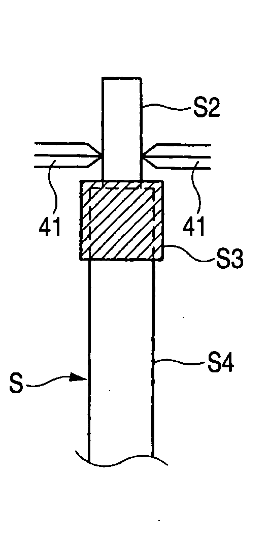
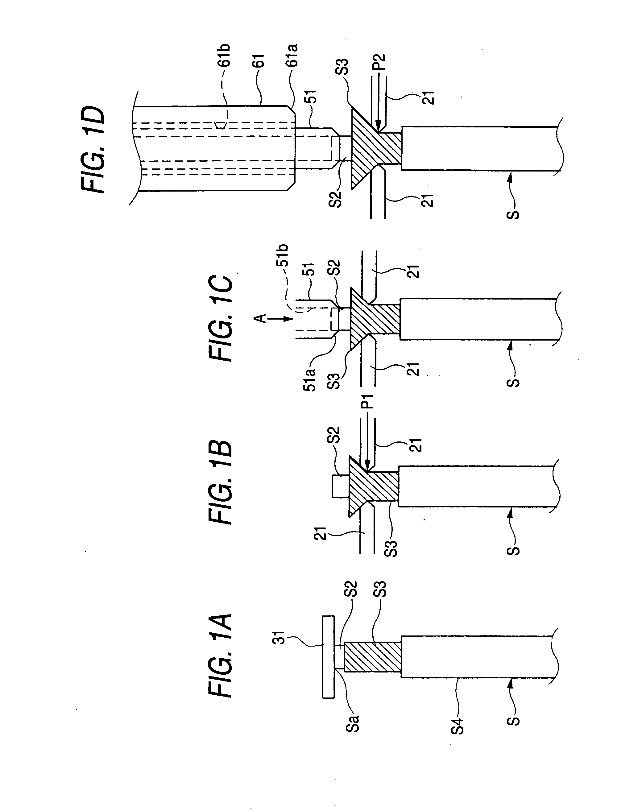
[0041]FIGS. 1A to 1D are views showing the steps of a shielded wire end processing method of the present invention;

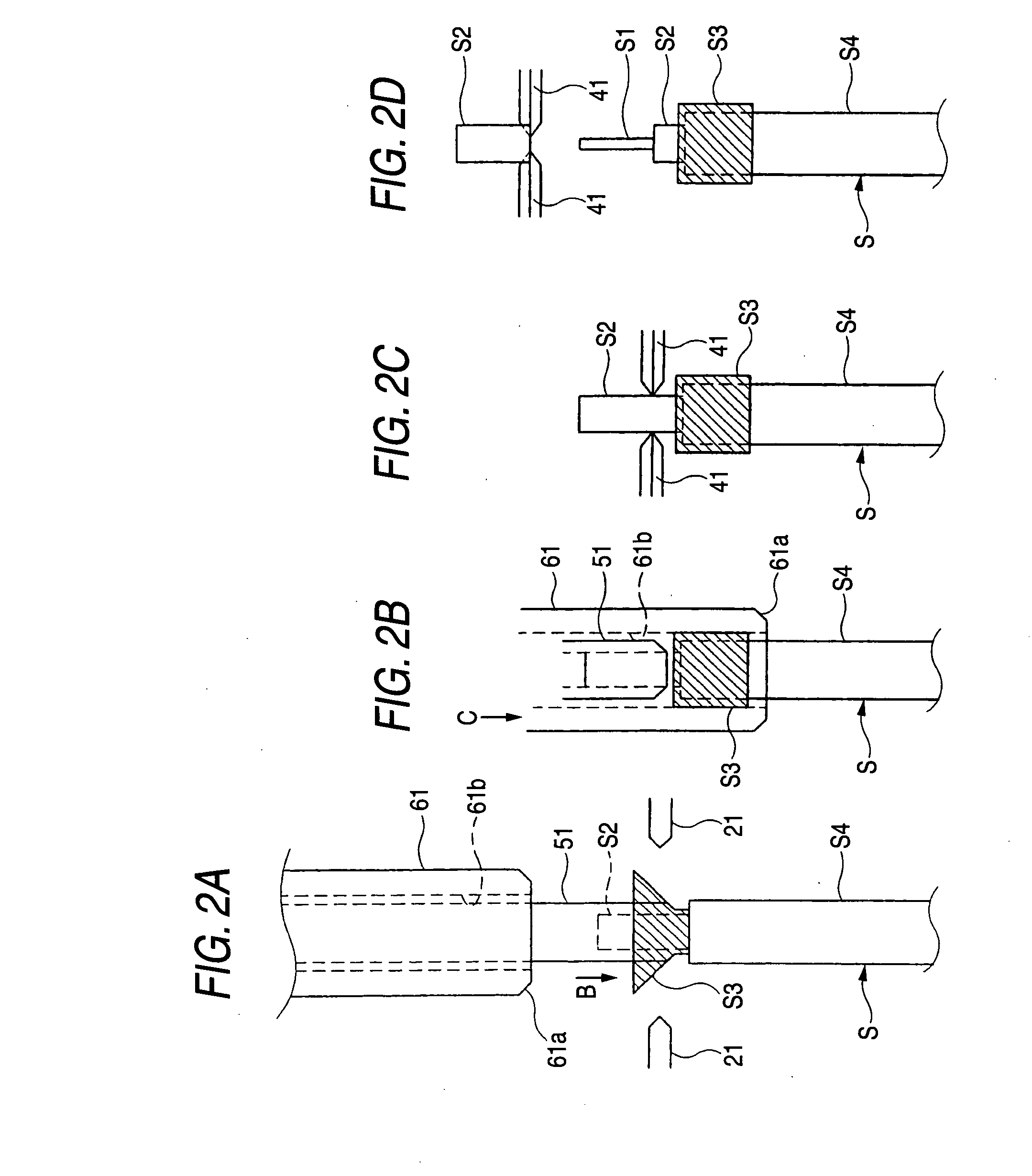
[0042]FIGS. 2A to 2D are views showing the steps subsequent to the steps of FIGS. 1A to 1D;

[0043]FIG. 3 is a partly cross-sectional, side-elevational view showing the broad construction of an important portion of a preferred embodiment of an end processing apparatus of the invention;

[0044]FIG. 4 is a view similar to FIG. 3, but showing an operated condition of the apparatus of FIG. 3; and

[0045]FIG. 5A is a perspective view showing the construction of a expansion claw used in the end processing apparatus, and FIG. 5B is a front-elevational view showing a pair of expansion claws in an assemb...


PUM

PropertyMeasurementUnit
angleaaaaaaaaaa
sizeaaaaaaaaaa
lengthaaaaaaaaaa

Abstract

An end portion processing apparatus for processing an end portion of a shielded wire in which part of an outer sheath has been removed such that an exposed braid disposed between an inner sheath and the outer sheath extends from a distal end of the outer sheath, includes a wire clamp portion which positions the end portion of the shielded wire in an open condition of the wire clamp portion, and clamps the end portion of the shielded wire, a pair of claw portions which strikes against the exposed braid radially thereof at the clamped end portion of the shielded wire to expand the end portion of the braid, a first pipe portion which is disposed in a standby position on a line of extension of the clamped end portion of the shielded wire, and is fitted onto an outer periphery of the inner sheath, a second pipe portion which is provided on an outer periphery of the first pipe portion in concentric relation thereto, and is slid toward the shielded wire to fold back the expanded braid on the outer sheath, and a control portion which controls the operations of the claw portions, the first pipe portion and the second pipe portion.

Description

BACKGROUND OF THE INVENTION[0001]This invention relates to a method of processing an end portion of a shielded wire and an end portion processing apparatus.[0002]In the case of applying an end processing to a shielded wire (or cable) including, for example, a core wire (center conductor), an inner sheath (inner layer) covering the conductor, a braid (shielding member) covering the inner sheath, and an outer sheath (outer covering) covering the braid, first, the outer sheath is stripped off or removed over a predetermined length at an end portion of the wire to expose the braid, and then the exposed braid is turned or folded back on the outer sheath, and then the exposed inner sheath is stripped off or removed to expose the conductor. Thus, these steps are carried out in this order.[0003]A problem with this end processing is the processing of the braid. This braid, after expanded into a generally trumpet bell-shape, need to be turned or folded back on the outer sheath, and this proce...

Claims


Application Information

Patent Timeline
Patent Type & Authority Applications(United States)
IPC IPC(8): H01R9/03H01R43/04B23P23/00
CPCH01R43/28Y10T29/514Y10T29/532Y10T29/4919Y10T29/49174Y10T29/49181Y10T29/49185Y10T29/49123H02G1/1258H02G1/1297
Inventor MATSUOKA, MASAKI
Owner YAZAKI CORP
Why Eureka
Try Eureka