Method of and system for stabilization of sensors

a technology for stabilizing sensors and sensors, applied in the field of methods and systems for stabilizing sensors, can solve the problems of patient inability to utilize a continuous glucose measurement system, glucose sensor not operating in a stable state, inconvenient patient, etc., and achieves faster run-in time, less background current, and better glucose response

Inactive Publication Date: 2007-07-26
MEDTRONIC MIMIMED INC
View PDF100 Cites 143 Cited by
  • Summary
  • Abstract
  • Description
  • Claims
  • Application Information

AI Technical Summary

Benefits of technology

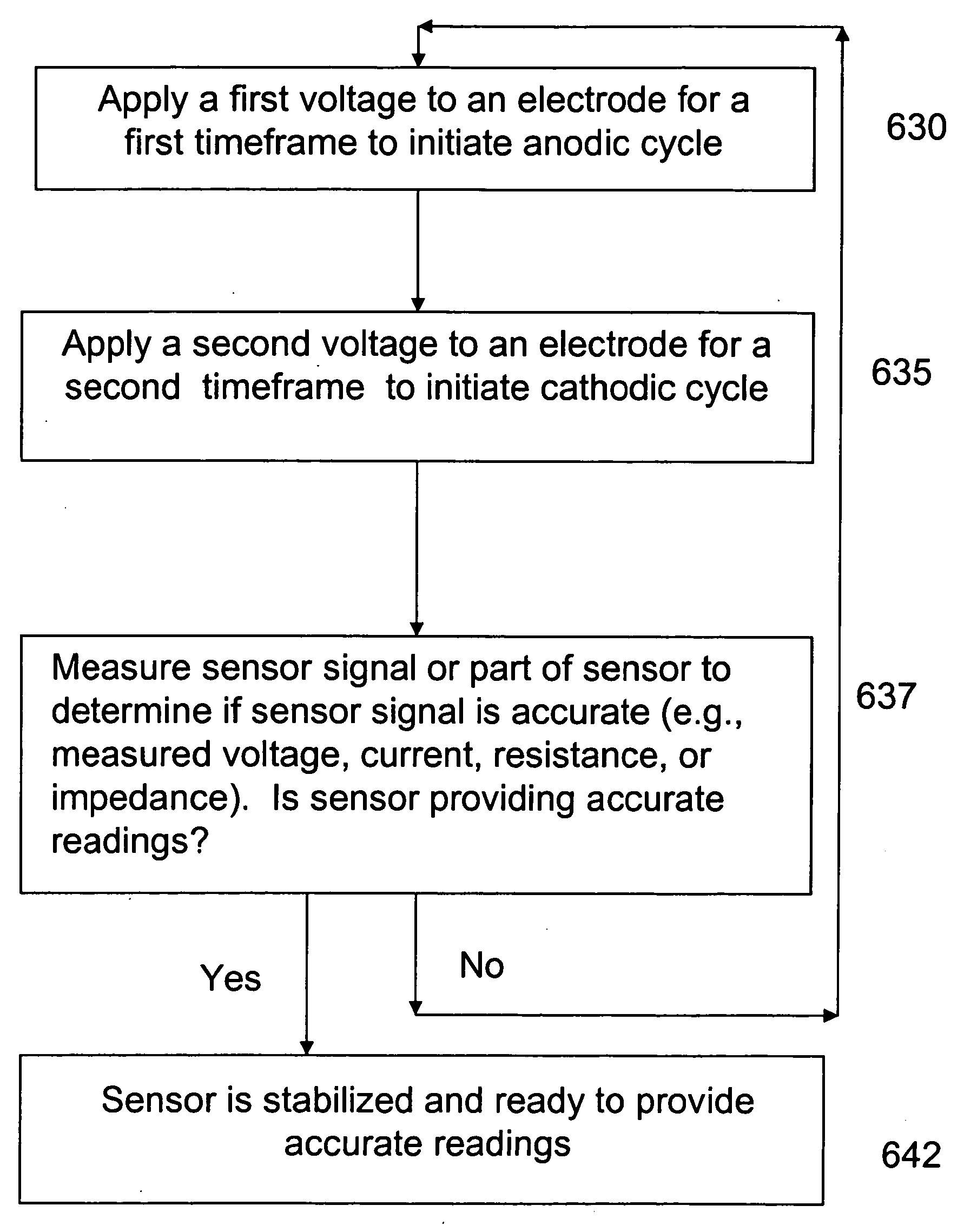
[0007]By utilizing the stabilization sequence identified above, the sensor has a faster run-in time, less background current exists in the sensor (due to suppression of background current, and the sensor has better glucose response. The first voltage may have a positive value or a negativ

Problems solved by technology

This is an inconvenience for the patient and in some cases may cause the patient not to utilize a continuous glucose measurement system.
Further, when a glucose sensor is first inserted into a patient's skin or subcutaneous layer, the glucose sensor does not operate in a stable state.
In the past, sensor stabilization used to take several hours.
Thus, even with this procedure, sensor stabilization still requires a large amount of time.
If the electrodes of the sen

Method used


Image

  • Method of and system for stabilization of sensors
  • Method of and system for stabilization of sensors
  • Method of and system for stabilization of sensors

Examples


second embodiment

[0107]FIG. 14(b) illustrates a combination of a hydration method and a stabilization method where feedback is utilized in the stabilization process. A sensor is connected 1405 to a sensor electronics device. An AC signal (or a DC signal) is applied 1411 to the sensor. In an embodiment of the invention, the AC signal (or the DC signal) is applied to an electrode of the sensor, e.g. the reference electrode. A impedance measuring device (or resistance measuring device) measures 1416 the impedance (or resistance) within a specified area of the sensor. In an embodiment of the invention, the impedance (or resistance) may be measured between the reference electrode and the working electrode. The measured impedance (or resistance) may be compared 1421 to an impedance or resistance value to see if the impedance (or resistance) is low enough in the sensor, which indicates the sensor is hydrated. If the impedance (or resistance) is below the impedance (or resistance) value or other set criteri...

third embodiment

[0108]FIG. 14(c) illustrates the invention where a stabilization method and hydration method are combined. In this embodiment of the invention, the sensor is connected 1500 to the sensor electronics device. After the sensor is physically connected to the sensor electronics device, an AC signal (or DC signal) is applied 1510 to an electrode (e.g., reference electrode) of the sensor. At the same time, or around the same time, the microcontroller transmits a signal to cause the DAC to apply 1520 a stabilization voltage sequence to the sensor. In an alternative embodiment of the invention, a stabilization current sequence may be applied to the sensor instead of a stabilization voltage sequence. The detection circuit determines 1530 what level of an AC signal (or DC signal) is present at an input terminal of the detection circuit. If there is a low level AC signal (or DC signal), representing a highly attenuated AC signal (or DC signal), present at the input terminal of the detection cir...


PUM


Abstract

A blood glucose sensing system includes a sensor and a sensor electronics device. The sensor includes a plurality of electrodes. The sensor electronics device includes stabilization circuitry. The stabilization circuitry cases a first voltage to be applied to one of the electrodes for a first timeframe and causes a second voltage to be applied to one of the electrodes for a second timeframe. The stabilization circuitry repeats the application of the first voltage and the second voltage to continue the anodic-cathodic cycle. The sensor electronics device may include a power supply, a regulator, and a voltage application device, where the voltage application device receives a regulator voltage from the regulator, applies a first voltage to an electrode for the first timeframe, and applies a second voltage to an electrode for the second timeframe.

Description

FIELD OF THE INVENTION[0001]Embodiments of this invention relate generally to methods and systems for stabilization of sensors during initial use of the sensors. More particularly, embodiments of this invention relate to systems and methods for providing an efficient way to stabilize the sensor in order for the sensor to provide accurate readings of a physiological condition of a subject.DESCRIPTION OF RELATED ART[0002]Subjects and medical personnel wish to monitor readings of physiological conditions within the subject's body. Illustratively, subjects wish to monitor blood glucose levels in a subject's body on a continuing basis. Presently, a patient can measure his / her blood glucose (BG) using a BG measurement device, such as a test strip meter, a continuous glucose measurement system, or a hospital hemacue. BG measurement devices use various methods to measure the BG level of a patient, such as a sample of the patient's blood, a sensor in contact with a bodily fluid, an optical s...

Claims


Application Information

Patent Timeline
IPC IPC(8): A61B5/05G01D18/00A61B5/00
CPCA61B5/14532A61B5/14865A61M2230/201A61B2560/0223A61M5/1723A61B5/4839G01N27/327A61B5/1495G01N27/3274
Inventor SHAH, RAJIVREGHABI, BAHARHENKE, JAMES L.MORGAN, WAYNE A.SOUNDARARAJAN, GOPIKRISHNANCHOY, DAVID Y.SCHULTZ, PETERHOSS, UDO
Owner MEDTRONIC MIMIMED INC
Why Eureka
Try Eureka