Touch panel, electrooptical device, and electronic apparatus

a technology of electrooptical devices and touch panels, applied in the direction of portable computer details, instruments, computing, etc., can solve the problems of frequent vibration and impact of mobile electronic devices, obstructing the surface acoustic waves, and malfunctioning, etc., to improve light availability, high brightness and contrast, and high position detection performance

Inactive Publication Date: 2007-08-02
JAPAN DISPLAY WEST
View PDF15 Cites 28 Cited by
  • Summary
  • Abstract
  • Description
  • Claims
  • Application Information

AI Technical Summary

Benefits of technology

[0009]An advantage of some aspects of the invention is that they provide a touch panel, an electrooptical device, and an electronic apparatus with high position detection performance.

Problems solved by technology

An obstacle on the SAW touch panel obstructs and absorbs the surface acoustic waves, which are received by the receiving transducers in a partially attenuated waveform.
Mobile electronic apparatuses experience frequent vibrations and impacts.
If the protective film is simply placed on the panel surface, a malfunction can occur when they become misaligned.
The attenuation of the surface acoustic wave due to the spacers is difficult to distinguish from attenuation of the surface acoustic wave due to touching.
The touch panel system therefore causes misdetection or malfunction and exhibits low position detection performance.

Method used


Image

  • Touch panel, electrooptical device, and electronic apparatus
  • Touch panel, electrooptical device, and electronic apparatus
  • Touch panel, electrooptical device, and electronic apparatus

Examples


first embodiment

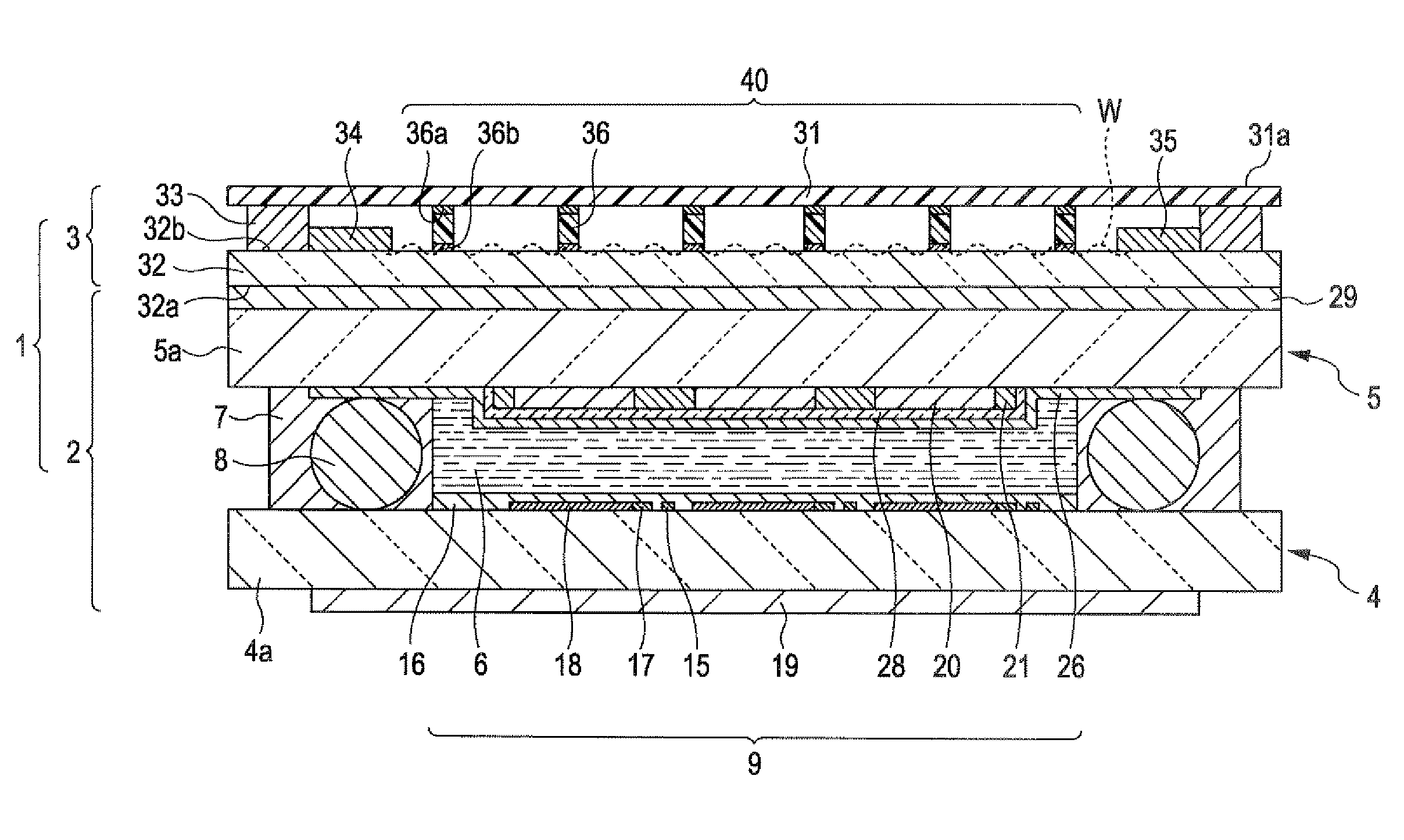
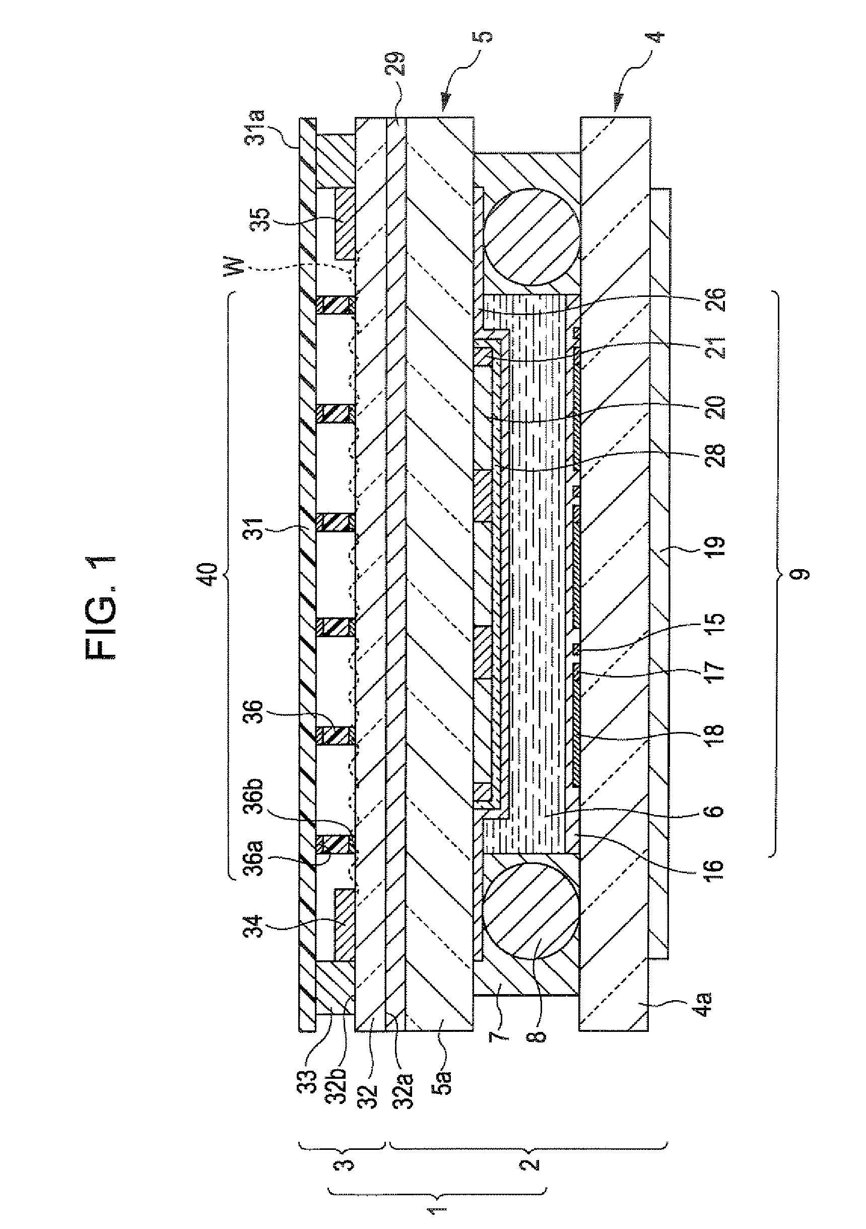
[0062]A touch-panel-equipped liquid crystal device according to a first embodiment of the invention will be described. FIG. 1 is a sectional view of a touch-panel-equipped liquid crystal device 1.

[0063]In FIG. 1, the liquid crystal device 1 mainly includes a liquid crystal panel 2 and a touch panel 3 bonded thereto. The liquid crystal device 1 according to this embodiment is of active matrix type, including thin-film transistors (TFTs) as switching elements for driving the liquid crystal device 1. The touch panel 3 includes chevron-shaped transducers.

[0064]First, the liquid crystal panel 2 will be described. This liquid crystal panel 2 includes a TFT array substrate 4, a color filter substrate 5 bonded thereto with a seal 7, and a liquid crystal layer 6 sealed within a region defined by the seal 7. A gap member 8 is provided in the seal 7 to define a gap between the TFT array substrate 4 and the color filter substrate 5. The region defined by the seal 7 functions as a display region...

second embodiment

[0089]A second embodiment of the invention will be described. In the drawings, as in the first embodiment, individual members are illustrated on different scales so that they have visible sizes. No description will be given of the same components as used in the first embodiment.

[0090]FIG. 5 is a sectional view of a touch-panel equipped liquid crystal device 101 according to this embodiment.

[0091]In FIG. 5, the liquid crystal device 101 mainly includes a liquid crystal panel 102 and a touch panel 103 bonded thereto, as in the first embodiment.

[0092]In this embodiment, a first touch panel substrate 131 of the touch panel 103 functions as a polarizer for the liquid crystal panel 102. Accordingly, a second touch panel substrate 132 of the touch panel 103 is directly bonded to a color filter substrate 105 of the liquid crystal panel 102 with no polarizer disposed therebetween. The rest of the structure of the liquid crystal device 101 is the same as in the first embodiment

[0093]According...

third embodiment

[0095]A third embodiment of the invention will be described. In the drawings, as in the first embodiment, individual members are illustrated on different scales so that they have visible sizes. No description will be given of the same components as used in the first embodiment.

[0096]FIG. 6 is a sectional view of a touch-panel-equipped liquid crystal device 201 according to this embodiment.

[0097]In FIG. 6, the liquid crystal device 201 mainly includes a liquid crystal panel 202 and a touch panel 203 bonded thereto, as in the first embodiment.

[0098]In this embodiment, a resin film 237 is bonded to an inner surface of a first touch panel substrate 231 of the touch panel 203 (facing the liquid crystal panel 202).

[0099]As in the second embodiment, additionally, the first touch panel substrate 131 functions as a polarizer for the liquid crystal panel 202. Accordingly, a second touch panel substrate 232 of the touch panel 203 is directly bonded to a color filter substrate 205 of the liquid...


PUM


Abstract

A touch panel includes a first touch panel substrate; a second touch panel substrate disposed opposite the first touch panel substrate; at least one surface acoustic wave generator that generates a surface acoustic wave propagating across a surface of the second touch panel substrate facing the first touch panel substrate in a predetermined direction; at least one surface acoustic wave sensor that senses the surface acoustic wave generated by the surface acoustic wave generator; a position detector that detects a position where the first touch panel substrate is pressed according to the waveform of the surface acoustic wave sensed by the surface acoustic wave sensor; and spacers disposed between the first and second touch panel substrates along a path where the surface acoustic wave propagates from the surface acoustic wave generator to the surface acoustic wave sensor.

Description

BACKGROUND[0001]1. Technical Field[0002]The present invention relates to touch panels, electrooptical devices, and electronic apparatuses.[0003]2. Related Art[0004]A surface acoustic wave (SAW) touch panel includes transmitting transducers that transmit surface acoustic waves propagating the panel surface and receiving transducers that receive the surface acoustic waves. An obstacle on the SAW touch panel obstructs and absorbs the surface acoustic waves, which are received by the receiving transducers in a partially attenuated waveform.[0005]The surface acoustic waves are absorbed when a user touches the SAW touch panel surface. The touch panel system measures the time that elapses before an attenuated waveform appears on the waveforms of the surface acoustic waves received by the receiving transducers. Based on the measurements, the touch panel system calculates the X and Y coordinates of a position touched by the user on the panel surface to detect the touched position. SAW touch ...

Claims


Application Information

Patent Timeline
Patent Type & Authority Applications(United States)
IPC IPC(8): G06F3/043
CPCG06F3/0436G06F3/0416G06F3/03547G06F1/169
Inventor ISHII, RYO
Owner JAPAN DISPLAY WEST
Why Eureka
Try Eureka