Subcutaneous ICD with separate cardiac rhythm sensor

a subcutaneous icd and cardiac rhythm technology, applied in the field of implantable medical devices, can solve the problems of limited atrial activation sensing, more challenging rhythm and arrhythmia sensing with the subq icd,

Active Publication Date: 2007-08-02
MEDTRONIC INC
View PDF13 Cites 45 Cited by
  • Summary
  • Abstract
  • Description
  • Claims
  • Application Information

AI Technical Summary

Problems solved by technology

The absence of endocardial or epicardial electrodes make rhythm and arrhythmia sensing more challenging with the SubQ ICD.
Sensing of atrial activation is limited since the atria represent a small muscle mass, and the atrial signals are not sufficiently detectable thoracically.

Method used


Image

  • Subcutaneous ICD with separate cardiac rhythm sensor
  • Subcutaneous ICD with separate cardiac rhythm sensor
  • Subcutaneous ICD with separate cardiac rhythm sensor

Examples


Embodiment Construction

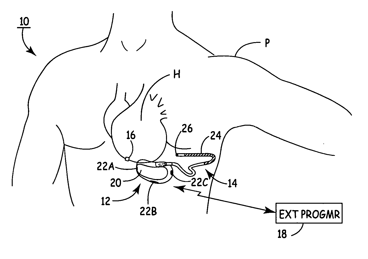
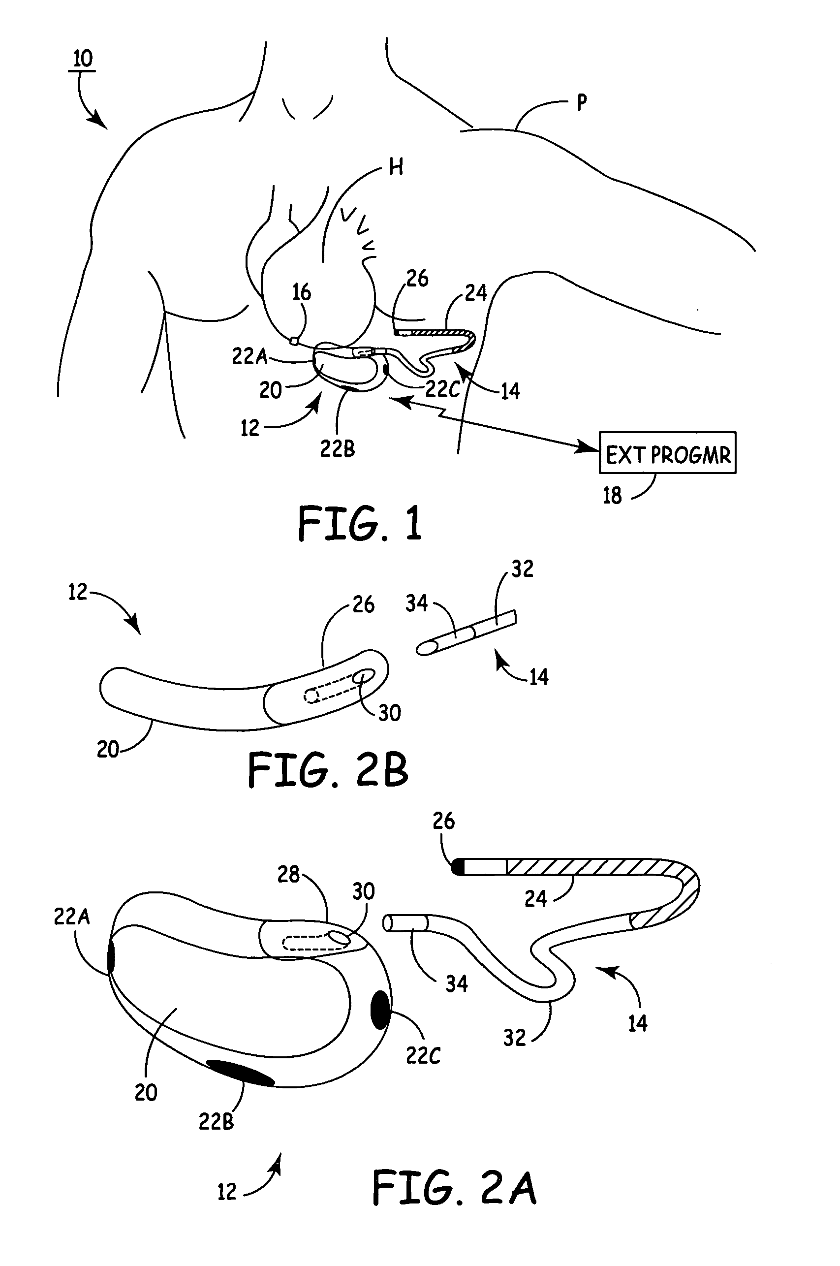
[0012]FIG. 1 shows implantable cardioverter defibrillator (ICD) system 10, which includes SubQ ICD 12, subcutaneous sensing and cardioversion / defibrillation therapy delivery lead 14, cardiac rhythm sensor 16, and external programmer 18.

[0013] Housing or canister 20 of SubQ ICD 12 is subcutaneously implanted outside the ribcage of patient P, anterior to the cardiac notch, and carries three subcutaneous electrodes 22A-22C. Lead 14 extends from housing 20 and is tunneled subcutaneously laterally and posterially to the patient's back at a location adjacent to a portion of a latissimus dorsi mucle. Electrode coil 24 and sensing electrode 26 are located at the distal end of lead 14. Heart H is disposed between the SubQ ICD housing 20 and distal electrode coil 24 of lead 14.

[0014] SubQ ICD 12 contains signal processing and therapy delivery circuitry to detect bradycardia and tachycardia conditions and to apply appropriate pacing and defibrillation shocking pulses to heart H. The pacing p...


PUM


Abstract

A cardiac rhythm sensor positioned on or close to the heart senses electrical or mechanical activity and transmits a cardiac rhythm signal wirelessly to a subcutaneous ICD. Arrhythmia detection and delivery of therapy are performed by the SubQ ICD based upon the cardiac rhythm signal received from the sensor.

Description

BACKGROUND OF THE INVENTION [0001] The present invention relates to implantable medical devices. In particular, the invention relates to a subcutaneous implantable cardioverter defibrillator (SubQ ICD) which receives a rhythm signal wirelessly from an implantable cardiac rhythm sensor positioned on or close to the epicardium. [0002] Implantable cardioverter defibrillators are used to deliver high energy cardioversion or defibrillation shocks to a patient's heart when atrial or ventricular fibrillation is detected. Cardioversion shocks are typically delivered in synchrony with a detected R-wave when fibrillation detection criteria are met. Defibrillation shocks are typically delivered when fibrillation criteria are met, and the R-wave cannot be discerned from signals sensed by the ICD. [0003] Currently, ICD's use endocardial or epicardial leads which extend from the ICD housing through the venous system to the heart. Electrodes positioned in or adjacent to the heart by the leads are ...

Claims


Application Information

Patent Timeline
Patent Type & Authority Applications(United States)
IPC IPC(8): A61N1/00
CPCA61B5/0031A61B5/042A61B5/0464A61N1/05A61N1/0587A61N1/3962A61N1/37252A61N1/37288A61N1/375A61N1/3756A61N1/37217A61N1/37518A61N1/39622A61B5/283A61B5/363A61B5/29
Inventor STEGEMANN, BERTHOLDBRUNS, HANS-JUERGEN
Owner MEDTRONIC INC
Why Eureka
Try Eureka