Method and apparatus for securing property from wind damage

Inactive Publication Date: 2007-08-16
JOHMER
View PDF21 Cites 11 Cited by
  • Summary
  • Abstract
  • Description
  • Claims
  • Application Information

AI Technical Summary

Problems solved by technology

Unfortunately, the disclosed invention does not provide for quick deployment when a storm is forecasted and safe removal after the storm passes.
Furthermore, the patent does not provide for roofs with gutter

Method used


Image

  • Method and apparatus for securing property from wind damage
  • Method and apparatus for securing property from wind damage
  • Method and apparatus for securing property from wind damage

Examples


second embodiment

[0027] Referring to FIG. 5, a detail view of a gutter guard of the present invention is shown. The gutter guard 20 has a base 21 that is a flat piece of sturdy material such as wood or plastic. In a preferred embodiment, the base 21 is made from plastic decking material, usually available in 1×6 or 2×6 configurations and preferably 3′ to 40 in length. The strap 10 passes over the base 21, which extends far enough beyond the roof 5 edge, so that the strap 10 is prevented from damaging the gutter 6. In some embodiments, brackets 22 with fasteners 24 hold the strap 10 in place on the gutter guard 20.

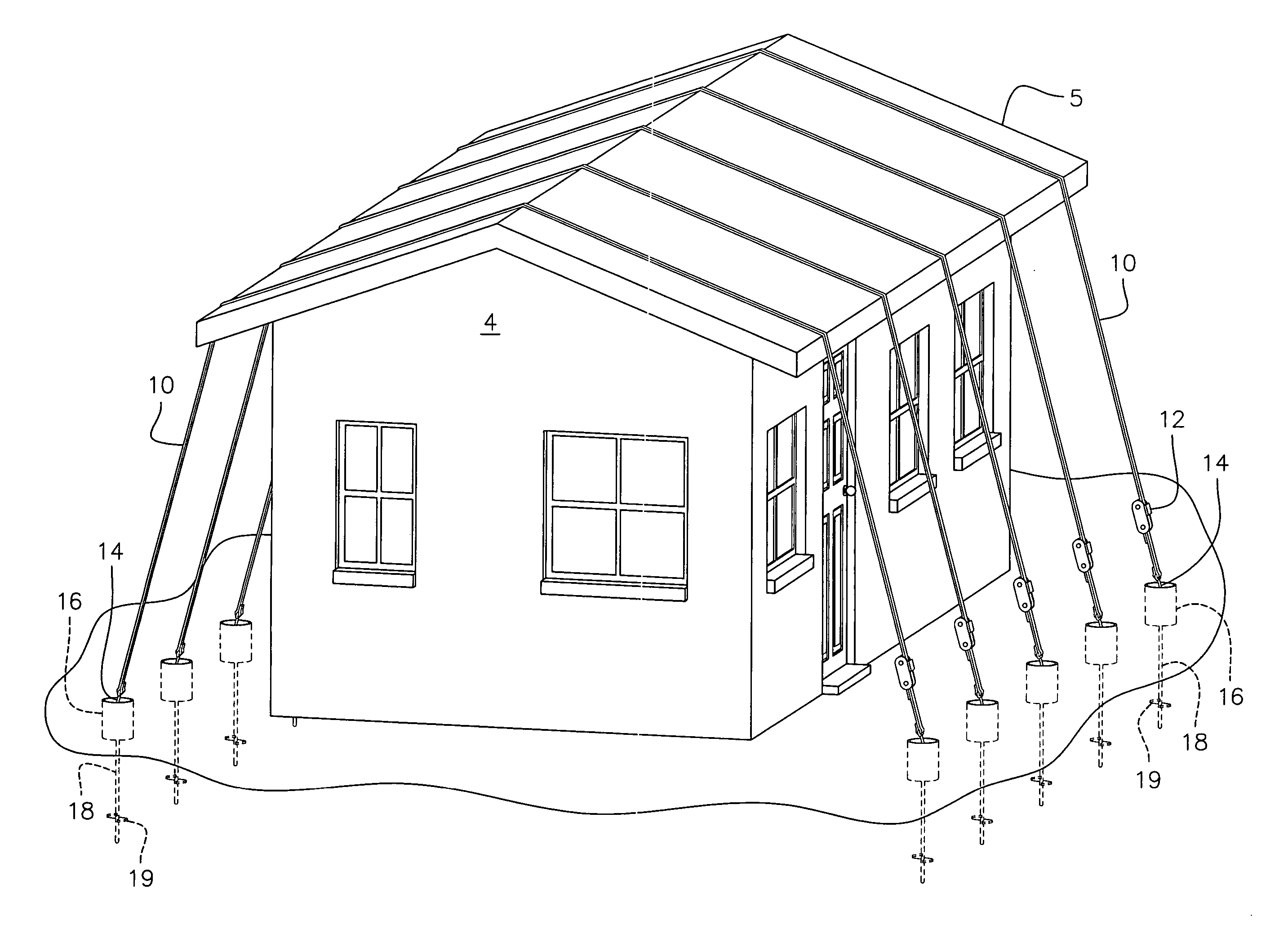
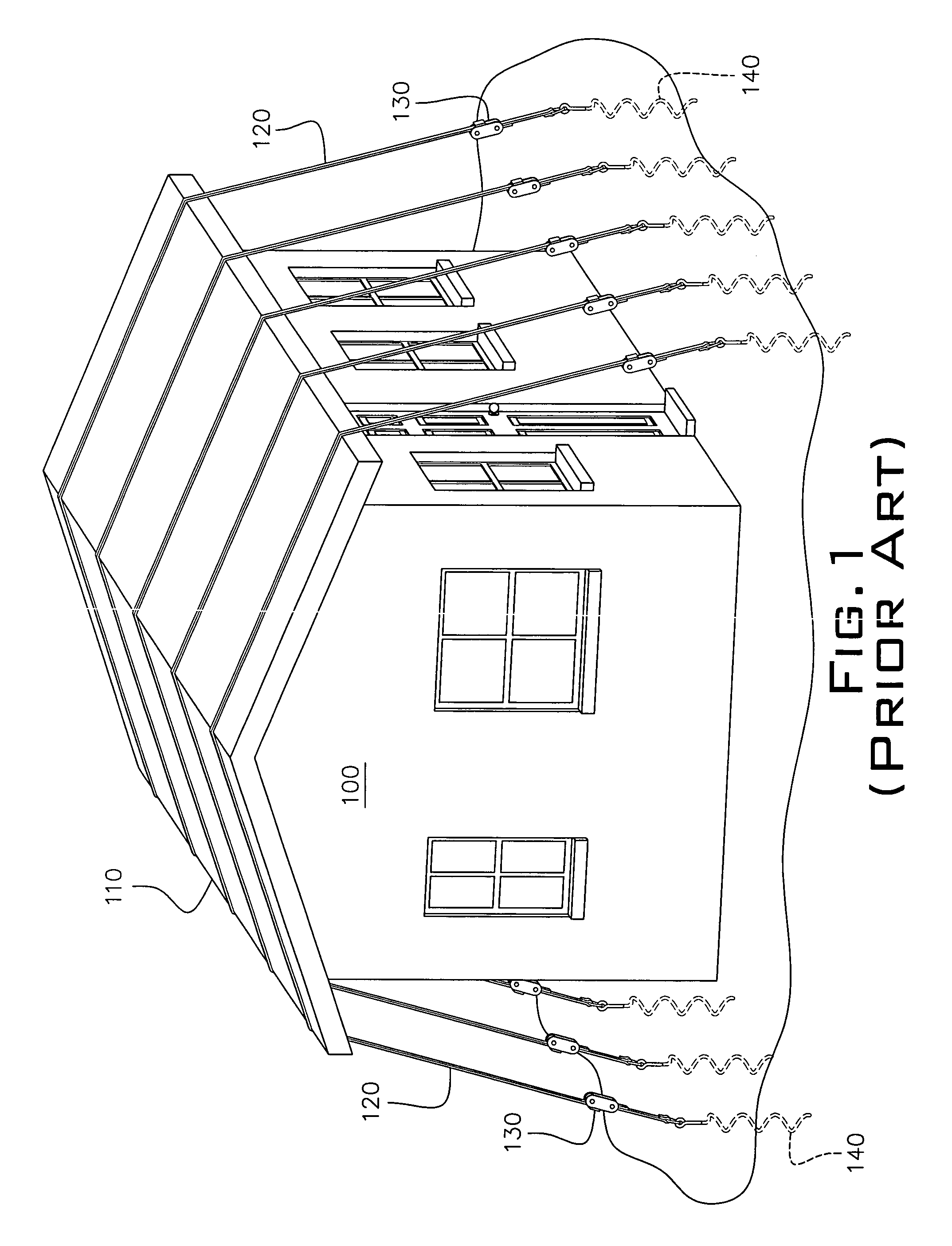
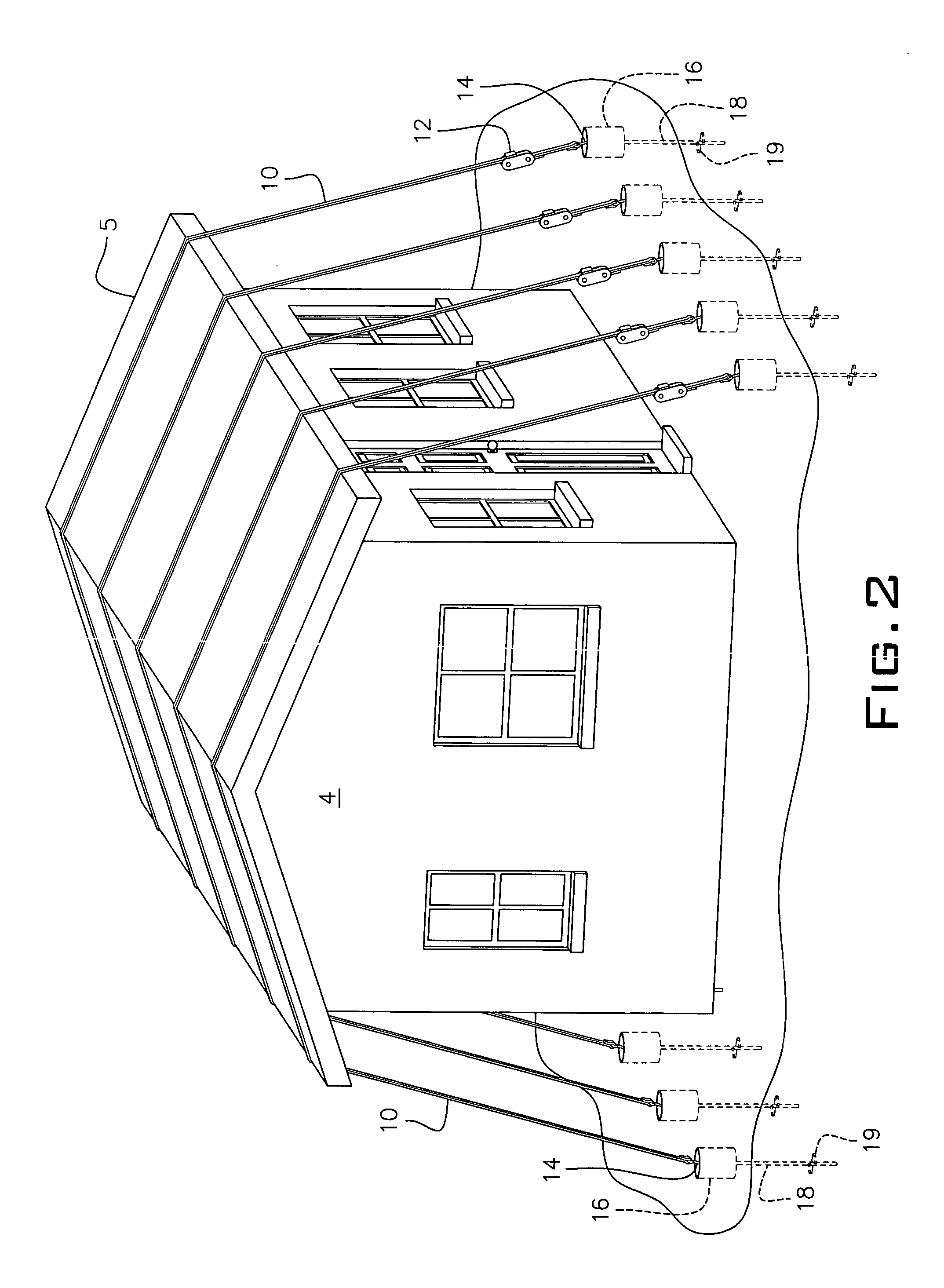
[0028] Referring to FIG. 6, a perspective view of a third embodiment of the present invention is shown. This embodiment has many of the same features of the first embodiment of FIG. 2. A plurality of straps 10 pass over the roof 5 of a structure 4. In this embodiment, the structure 4 has ridge vents 8 at the peak of the roof 5. If the straps 10 were attached as in FIG. 2, the tension of the...

third embodiment

[0031] Referring to FIG. 7, a detail view of a ridge vent guard of the present invention is shown. The ridge vent guard 30 sits on the roof 5 and holds the strap 10 away from the ridge vent 8, protecting it from being damaged by the strap 10. In this embodiment, the ridge vent guard is triangular in shape, comprising a base member 30c resting on the roof surface, a riser member 30a and a longer member 30b, providing structural strength when the strap 10 is tensioned. Also, in this embodiment, a cross member 30d is provided to space the individual ridge vent guards 30 and hold them in position while the straps 10 are being installed and tensioned. In some embodiments, there are no cross members 30d and the ridge vent guards 30 stand independently.

[0032] Referring to FIG. 8, a perspective view of all embodiments of the present invention is shown. In this, the strap system of the previous embodiments is removed, perhaps during a season when there is little chance of storms or when no s...

first embodiment

[0036] Although the guard systems are described as separate embodiments, it is not intended to be limited in any way, such that depending upon the structure being protected, the protection system of the first embodiment stands alone or in another It is believed that the system and method of the present invention and many of its attendant advantages will be understood by the foregoing description. It is also believed that it will be apparent that various changes may be made in the form, construction and arrangement of the components thereof without departing from the scope and spirit of the invention or without sacrificing all of its material advantages. The form herein before described being merely exemplary and explanatory embodiment thereof. It is the intention of the following claims to encompass and include such changes. What is claimed is:


PUM


Abstract

A series of screw-type anchors are set around the periphery of the structure. The anchors are set below the ground surface and enclosed in recess pots to provide access, helping to keep soil from covering the anchors. When a storm is predicted, a plurality of straps are passed over the roof and hooked into the anchors. The straps have a ratchet at one end to tighten the straps and provide tension to the roof. Gutter guards are optionally provided to protect a gutter from damaged by the straps. Ridge vent guards are also optionally provided to protect a ridge vent from damage by the straps. Recess pot covers are provided to reduce the chances of tripping.

Description

BACKGROUND OF THE INVENTION [0001] 1. Field of the Invention [0002] The present invention relates to the field of protecting roofs of buildings to prevent damage during storms and more particularly to a method and apparatus for securing an roof of a building to prevent or reduce damage during a severe storm such as a hurricane. [0003] 2. Description of the Related Art [0004] Many, hold-down systems have been designed to prevent or reduce damage to structures occurring during severe storms such as hurricanes and tornadoes. The art has many examples of ways to protect building structures with roofs during severe storms, including U.S. Pat. No. 5,570,545, “Apparatus for Holding a Roof on a Building during High Winds,” to Adams, which is hereby incorporated by reference. This patent describes a system of straps that are passed across a roof of a structure then tensioned to anchors. Unfortunately, the disclosed invention does not provide for quick deployment when a storm is forecasted an...

Claims


Application Information

Patent Timeline
IPC IPC(8): E04B7/00
CPCE04H9/14Y02A50/00
Inventor OSBON, HOMER C.CARVALIS, JOHN E.
Owner JOHMER
Why Eureka
Try Eureka