
Hurricane cable system and method of use therof

a technology of hurricane cable and cable system, which is applied in the field of hurricane cable system, can solve the problems of a large amount of damage, and the most susceptible to wind damage in residential homes, with their wood frame construction and numerous windows

Inactive Publication Date: 2011-02-17
CURRY CO
View PDF13 Cites 7 Cited by
  • Summary
  • Abstract
  • Description
  • Claims
  • Application Information

AI Technical Summary

Benefits of technology

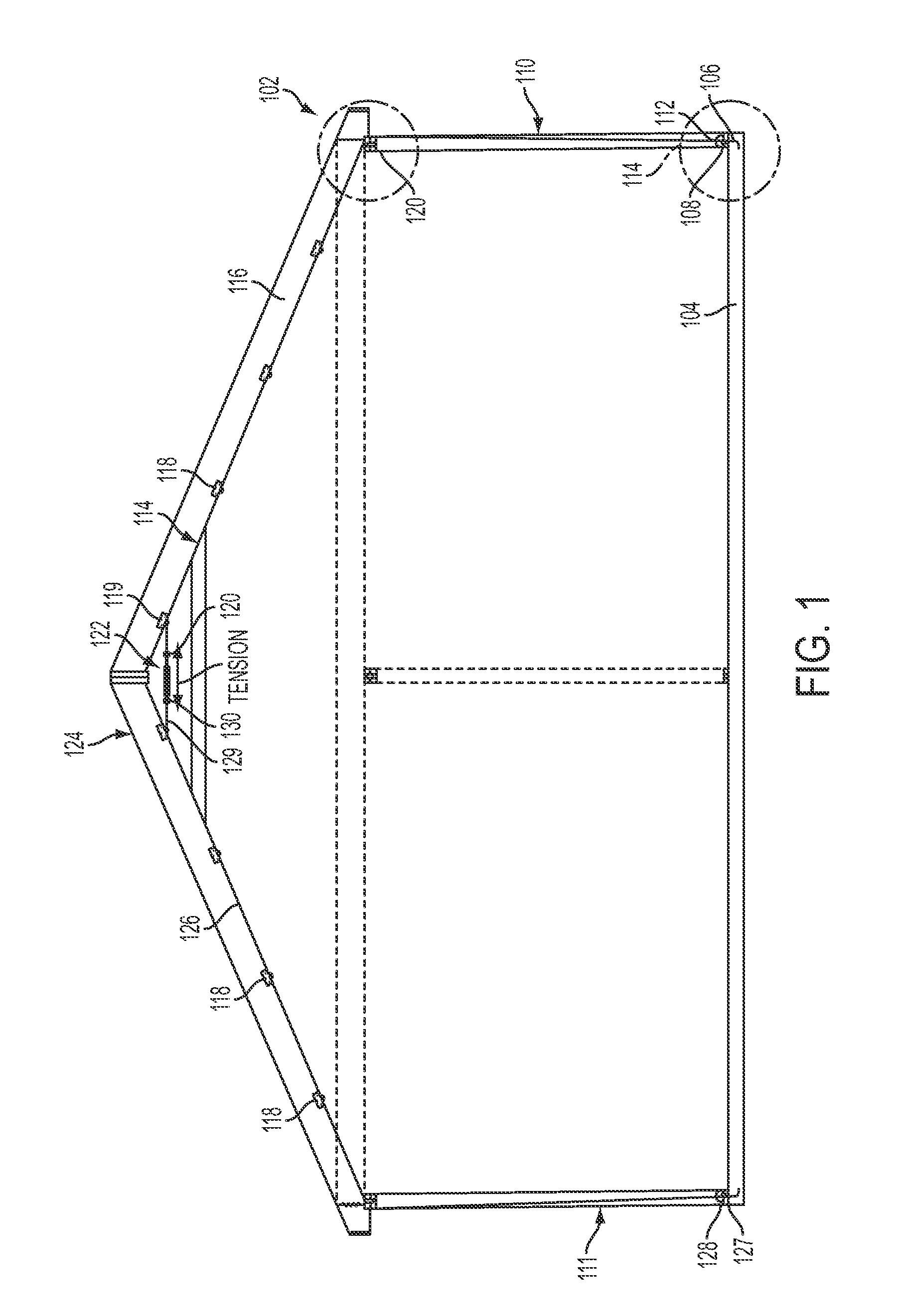
[0012]According to yet another aspect, the present invention provides a method for resisting catastrophic wind damage to a structure having a roof, opposite sidewalls and a foundation. The method includes fixing a first anchoring device and a second anchoring device to the foundation at positions adjacent to the sidewalls, respectively. The method includes attaching a first cable to the first anchoring device and a second cable to the second anchoring device. The method includes disposing a tensioning member under the roof and between the sidewalls. The method includes attaching the tensioning member to both the first cable and the second cable. The method further includes applying a tension force to the first cable and the second cable through the tensioning member.

Problems solved by technology

Each year hurricanes, nor'easters, and other extreme-wind storms result in billions of dollars in damage.
While flooding caused by hurricanes receives greater attention, a significant portion of damage is the result of the high winds experienced by building structures that were not built to withstand such forces.
Residential homes, with their wood-frame construction and numerous windows, are most susceptible to wind damage.
Often severe winds can literally tear roofs from homes because of pressure differences between the internal pressure of the house and the external pressures resulting from the high wind.
The low pressure lift forces that result in most roof damage is caused by wind traveling further along one plane of a roof versus the other plane.
This often results in damage or even catastrophic failure of the roof structure in cases where the wind speed is high enough.

Method used


Image

  • Hurricane cable system and method of use therof
  • Hurricane cable system and method of use therof
  • Hurricane cable system and method of use therof

Examples


Embodiment Construction

[0022]Hereinafter, all similar elements shown in the figures are referenced with identical reference numerals.

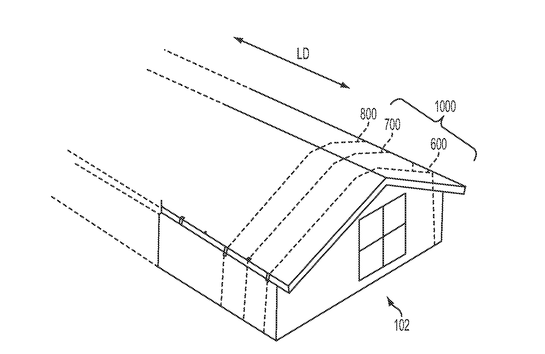
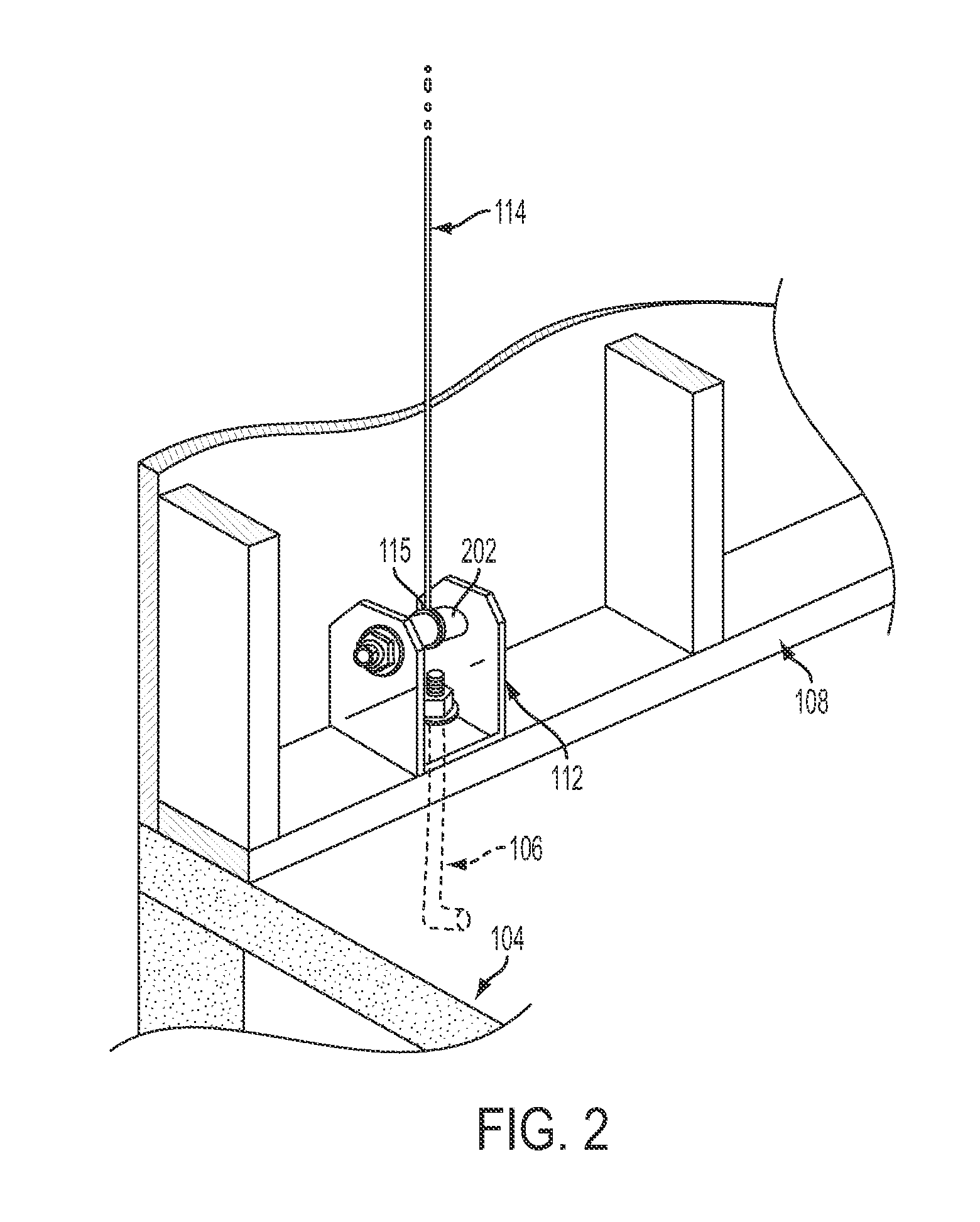
[0023]Referring to FIGS. 1-4, an embodiment of the present invention is shown installed in a house 102. As shown, the house 102 is constructed on a foundation slab 104. An anchor 106 is embedded into the foundation slab 104 through a sill plate 108 of a sidewall 110. The anchor 106 securely holds an anchor bracket 112 to the foundation slab 104. The house 102 further includes a sidewall 111, opposite to the sidewall 110.

[0024]As shown in FIG. 2, the anchor 106 is dimensioned as an L-shaped bolt, where the 90° bend resides within or under the foundation slab 104. This shape provides a strong attachment to the foundation slab 104. However, alternative shapes may be used as well. For example, T-shaped or J-shaped anchor bolts can be used, as well as an anchor bolt having multiple arms extending perpendicular and radial from the central bolt shaft.

[0025]While the anchor shapes d...


PUM


Abstract

A system and method for resisting catastrophic wind damage to a structure is provided. At least a pair of anchoring devices are fixed to a foundation of the structure at opposite positions adjacent to sidewalls of the structure. A first cable and a second cable are attached to the anchoring devices, respectively. A tensioning member is provided under a roof of the structure and between the sidewalls of the structure. The tensioning member, such as a turnbuckle, is further attached to both the first and second cables for applying a tension force to the cables. Cable guides can be further provided to route the cables along the roof and sidewalls of the structure.

Description

FIELD OF THE INVENTION[0001]The present invention relates generally to building construction; and more specifically, the present invention relates to a hurricane cable system and method of use thereof for maintaining structural integrity under high wind conditions.BACKGROUND OF THE DISCLOSURE[0002]Each year hurricanes, nor'easters, and other extreme-wind storms result in billions of dollars in damage. While flooding caused by hurricanes receives greater attention, a significant portion of damage is the result of the high winds experienced by building structures that were not built to withstand such forces.[0003]Residential homes, with their wood-frame construction and numerous windows, are most susceptible to wind damage. Often severe winds can literally tear roofs from homes because of pressure differences between the internal pressure of the house and the external pressures resulting from the high wind. The low pressure lift forces that result in most roof damage is caused by wind...

Claims


Application Information

Patent Timeline
IPC IPC(8): E04H9/14E04B7/18E04B1/38
CPCE04H9/14Y02A50/00
Inventor CURRY, III, JAMES
Owner CURRY CO
Learn More