

Friction stabilizer with tabs
- Summary
- Abstract
- Description
- Claims
- Application Information
AI Technical Summary
Benefits of technology
Problems solved by technology
Method used
Image

Examples
Example
[0081]FIG. 11 is a sectional view of the tubular body of the second embodiment taken along cut line 11-11 of FIG. 10, and FIG. 12 is a sectional view of the tubular body of the second embodiment taken along cut line 12-12 taken of FIG. 8. The tubular body 22a can be used for supporting the walls 52 and ceiling 54 of a mine 56 in the same manner as previously described in connection with the first embodiment.
Example
[0082]FIGS. 13-17 generally show a third embodiment of the friction stabilizer 20b with tabs. In this embodiment, the tubular body 22b comprises triangular shaped tabs 41. The tubular body 22b of the third embodiment is substantially the same as the tubular body 22 of the first embodiment, in that the tubular body 22b comprises an exterior surface 26, first and second gap space walls 27,29, respectively, a tube gap space 28, an impact end 30, insertion end 32, a rectangular weld ring 31 having a weld ring gap space 39, a first portion 33, and a second portion 34 having a taper 35 having a notch. Each triangular shaped tab 41 of the third embodiment has two edges 46 that meet at a point 47, thus forming a triangle shape. The triangular shaped tabs 41 are joined to the tubular body 22b at bends 44, as shown. There is a row 129 of triangular shaped tabs 41 that extend from the tubular body 22b at predetermined spaced intervals, designated I in FIG. 13, along the length L of the tubular...
Example
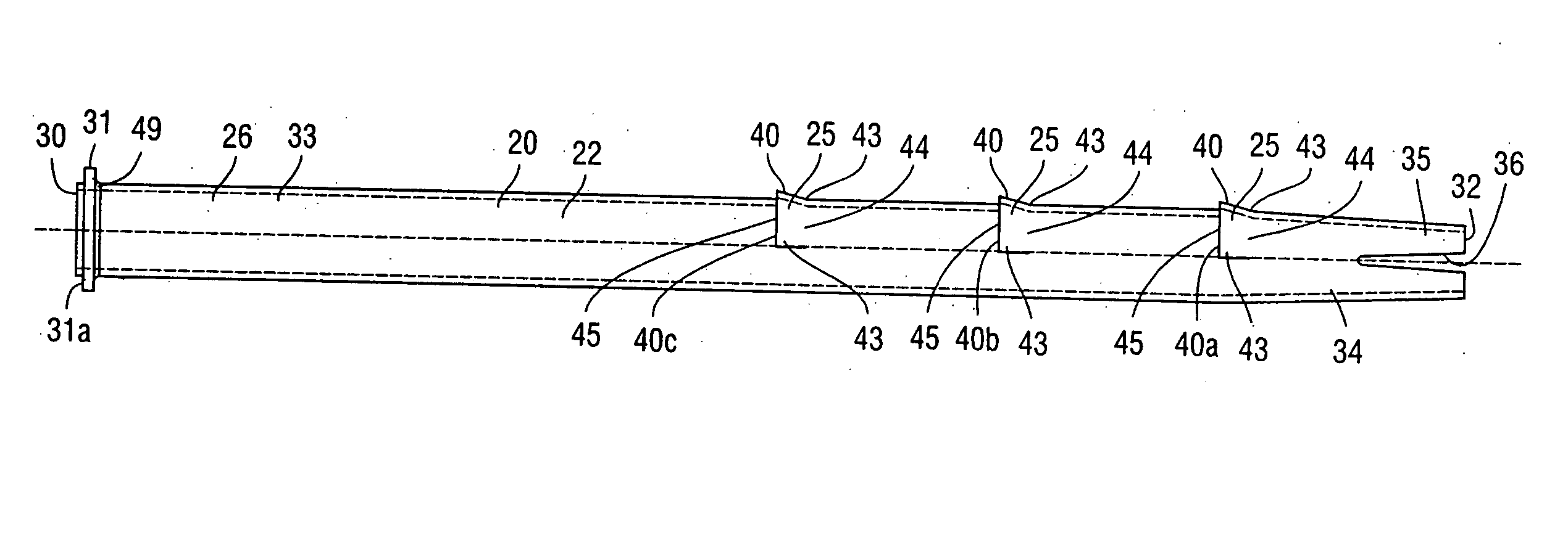
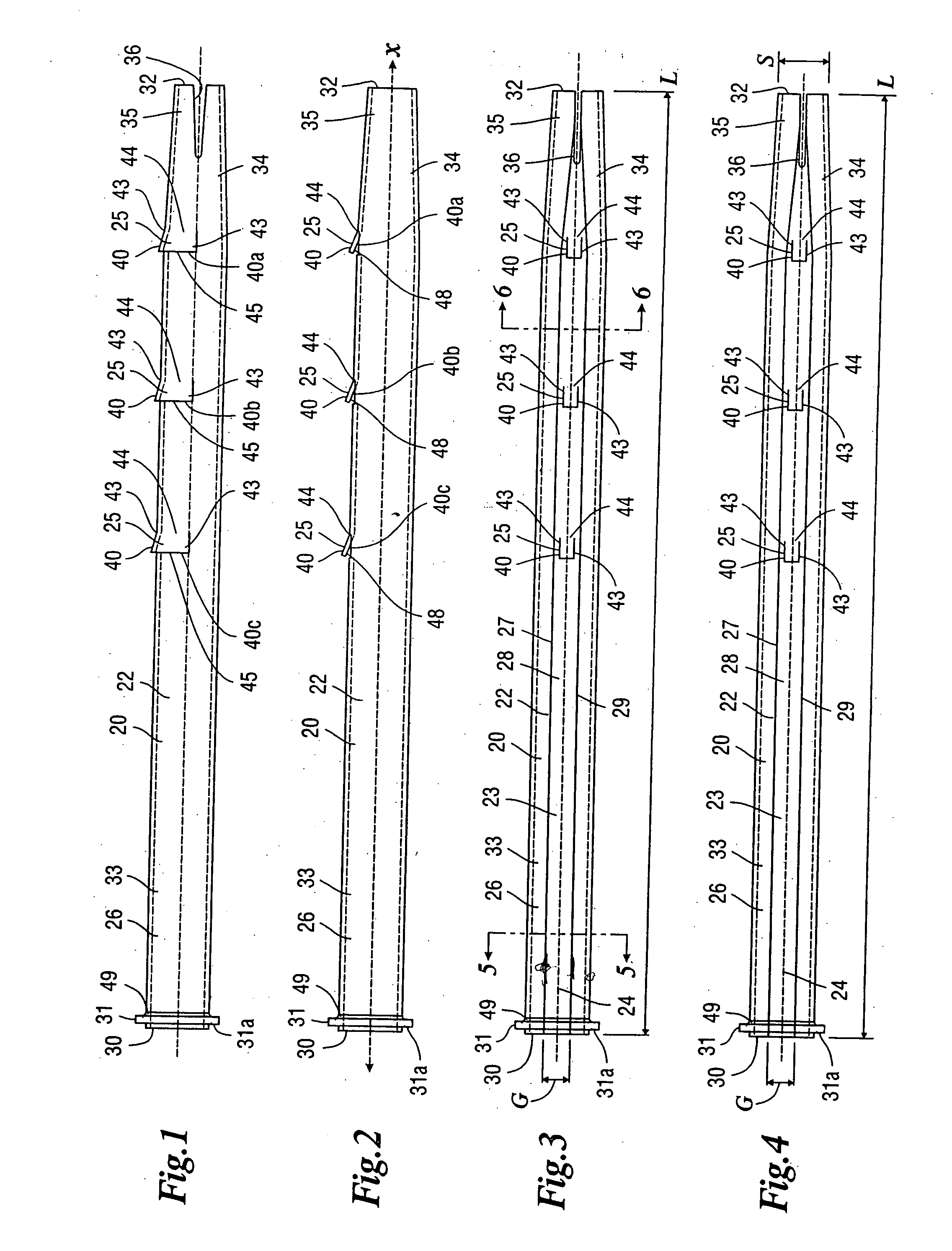
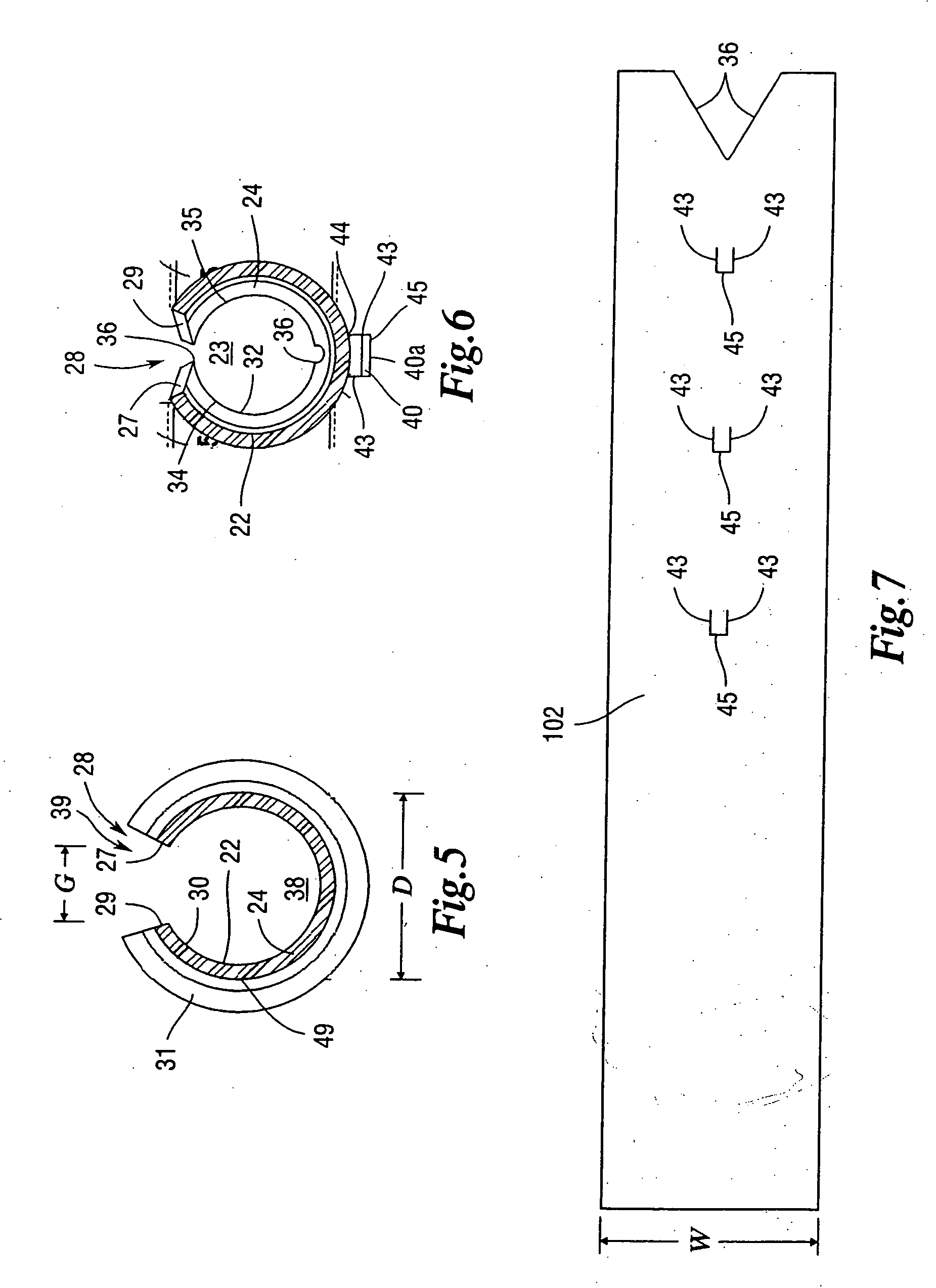
[0084]FIGS. 18-22 generally show a fourth embodiment of the friction stabilizer 20c with tabs. In the fourth embodiment, the tubular body 22c comprises a plurality of rows 128 of rectangular shaped tabs 40. The rectangular shaped tabs 40 in each row 128 are spaced from one another, and the rows 128 are spaced about ninety degrees from one another about the exterior surface 26 of the tubular body 22c, as viewed in sectional FIGS. 21 and 22. The tubular body 22c of the fourth embodiment is substantially the same as the tubular body 22 of the first embodiment, in that the tubular body 22c comprises an exterior surface 26, first and second gap space walls 27,29, respectively, a tube gap space 28, an impact end 30, insertion end 32, a rectangular weld ring 31 having a weld ring gap space 39, a first portion 33, and a second portion 34 having a taper 35 having a notch. Each rectangular shaped tab 40 of the fourth embodiment is joined to the tubular body 22c at a bend 44, and extends in a ...
PUM
 Abstract
Description
Claims
Application Information