
Removable side hinge for appliance

Active Publication Date: 2013-05-30
BSH HOME APPLIANCES CORP
View PDF4 Cites 0 Cited by
  • Summary
  • Abstract
  • Description
  • Claims
  • Application Information

AI Technical Summary

Benefits of technology

The invention provides a hinge that allows the top of a door with a built-in oven to be pivoted down while keeping both the top and bottom of the door attached to the oven body. The hinge also provides a retention mechanism that prevents the door from falling and becoming detached from the oven body at its maximum pivoting position. This makes it safer for a technician to remove the door while supporting it.

Problems solved by technology

Such an arrangement can make it difficult or impossible to remove a door from the oven without removing the oven from the cabinet into which it is built.
In the built-in arrangement, it is often not possible to access the hinges to remove the hinge pins.
Removing the oven, even partially, from the cabinet can be difficult and dangerous due to the large size and weight of some ovens.
With a built-in oven that has a control panel positioned above and in close proximity to the top of a side swinging door, it can be difficult, or even impossible, to remove the door without at least partially removing the oven from the cabinet or wall.

Method used


Image

  • Removable side hinge for appliance
  • Removable side hinge for appliance
  • Removable side hinge for appliance

Examples


Embodiment Construction

[0020]The invention is described herein with reference to the accompanying drawings in which exemplary embodiments of the invention are shown. The invention may, however, be embodied in many different forms and should not be construed as limited to the embodiments set forth herein.

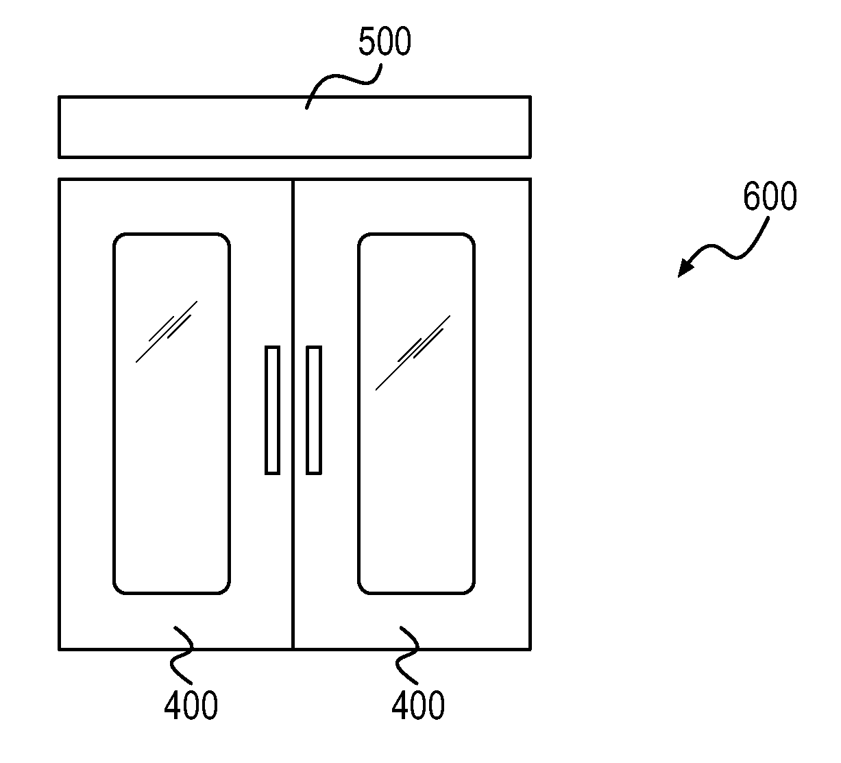
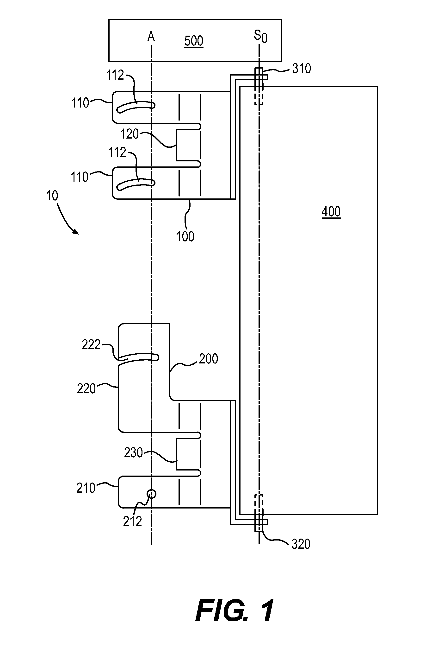
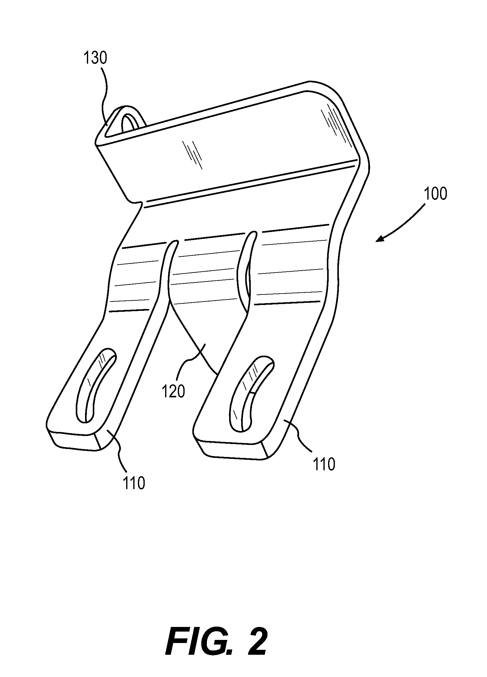
[0021]FIGS. 1, 9 and 10 show examples of a hinge assembly 10 in accordance with an embodiment of the invention. Hinge assembly 10 includes an upper hinge bracket 100 and a lower hinge bracket 200. Upper hinge bracket 100 is attached to a door 400 by a hinge pin 310. Lower hinge bracket 200 is attached to door 400 by a hinge pin 320. Pins 310 and 320 can be any suitable pivoting attachment mechanism. In this example, door 400, 400′ is a side swing door of a domestic kitchen oven 600, 600′ and swings about a swing axis S0. Upper hinge bracket 100 and lower hinge bracket 200 are attached to a frame or other structural part of the oven so as to attach door 400 to the oven. A control panel 500 of the oven locat...


PUM


Abstract

A hinge system for mounting a door to an appliance has an upper hinge bracket having an upper hinge swing element configured to engage a door upper swing element fixed to the door, the engagement of the upper hinge swing element and the door upper swing element allowing the door to swing about a vertical axis between an open position and a closed position, and an upper hinge pivot limiting element configured to engage a frame pivot limiting element fixed to the appliance; a lower hinge bracket having a lower hinge swing element configured to engage a door lower swing element, and a system pivot element configured to engage a frame pivot element such that the upper hinge bracket, the lower hinge bracket, and the door are pivotable about a horizontal axis as a unit relative to the appliance while still being attached to the appliance.

Description

FIELD OF THE INVENTION[0001]The invention is directed to a hinge system for a side swing door. More particularly, the invention is directed to a hinge system that allows a side swing door to be tilted for safe removal of the door from an appliance.[0002]An example of an application for the invention is a hinge system that attaches a side swing door to a domestic oven. By allowing the top of the door to pivot about a horizontal axis away from the oven while limiting how far the door pivots, the door can be pivoted far enough to remove a top hinge pin and permit safe removal of the door.BACKGROUND OF THE INVENTION[0003]Some domestic appliances, such as built in ovens, have one or more doors that each swing sideways about a vertical axis. Particular side swing doors have hinges that permit the door to swing about the vertical axis between a closed position and an open position. In some of these built-in ovens, a control panel is positioned above the door in close proximity to the top o...

Claims


Application Information

Patent Timeline
IPC IPC(8): A47B81/00E05D11/10
CPCE05Y2900/308E05D3/022E05D3/10E05D3/18E05D7/04Y10T16/54E05Y2800/744E05D11/10Y10T16/5406Y10T16/5407E05D7/081F24C15/023
Inventor ELKASEVIC, SUADGEIGER, JOSEPHWEIMER, CHARLESWIESER, PHILIPP
Owner BSH HOME APPLIANCES CORP
Learn More