
Novel steel bar hoop bending equipment

A technology of steel bar bending hoops and equipment, applied in the direction of conveyor objects, transportation and packaging, conveyors, etc., can solve the problems of high labor intensity and adverse effects of steel bars, and achieve the advantages of reducing labor intensity, avoiding work, and high ease of operation Effect

Pending Publication Date: 2022-05-06
湖北舜安建设工程有限公司
View PDF0 Cites 0 Cited by
  • Summary
  • Abstract
  • Description
  • Claims
  • Application Information

AI Technical Summary

Problems solved by technology

[0003] Some of the existing steel bar bending hoop equipment is not equipped with a collection device, and the steel bar directly falls to the bottom surface after being bent and cut; It may have adverse effects on the steel bars after bending hoops; some are equipped with a collection device, which is a rotatable and feedable stand, and the top of the stand is provided with several upward-sloping hanging rods, and the cut steel bars fall Slide to the hanging rods, and after each hanging rod has enough weight, the steel bars on the hanging rods need to be removed. Since the hanging rods are set upwards, the position of the steel bars needs to be raised to the top of the hanging rods when removing them. This process The operator needs to bear the weight of the steel bar, so the labor intensity is high

Method used


Image

  • Novel steel bar hoop bending equipment
  • Novel steel bar hoop bending equipment
  • Novel steel bar hoop bending equipment

Examples


Embodiment Construction

[0040] The technical solution of the present invention will be clearly and completely described below in conjunction with the accompanying drawings and specific embodiments. Apparently, the described embodiments are only some of the embodiments of the present invention, not all of them. Based on the embodiments of the present invention, all other embodiments obtained by persons of ordinary skill in the art without creative efforts fall within the protection scope of the present invention.

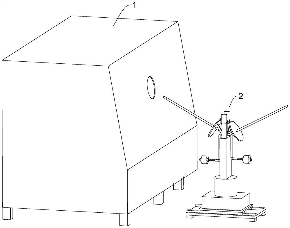
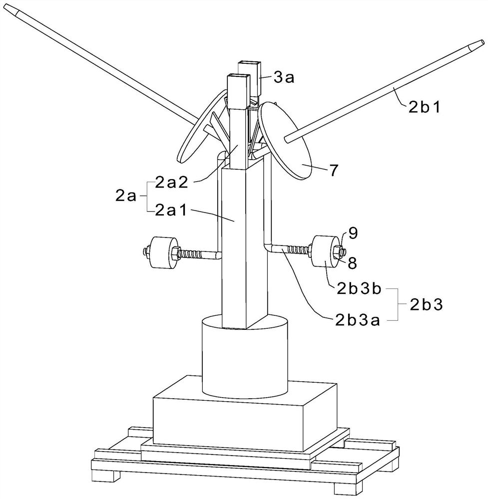
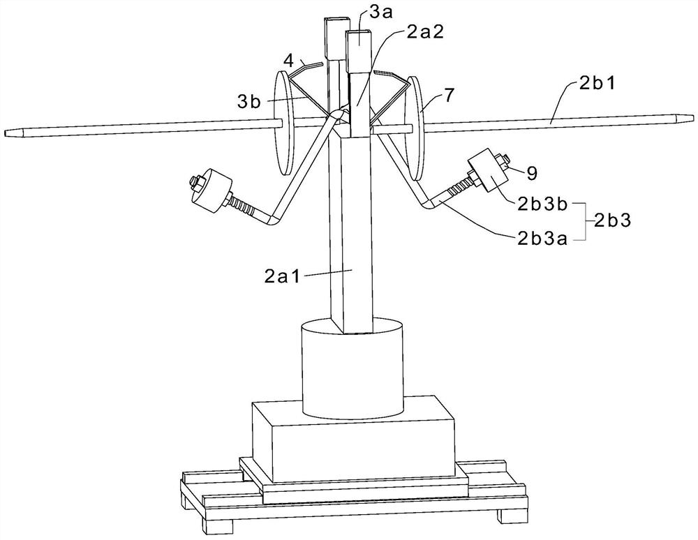
[0041] A kind of novel steel bar bending hoop equipment provided by the invention, such as Figure 1 to Figure 7 As shown, it includes a body 1 and a collection mechanism 2, the collection mechanism 2 includes a rotatable and feedable support structure 2a and two hanging rods 2b, the length directions of the two hanging rods 2b are parallel in the horizontal direction , the hanging rod 2b includes a hanging part 2b1 for hanging the steel bar after the hoop, a hinged part 2b2 hinged with th...


PUM


Abstract

The invention relates to the technical field of reinforcing steel bar machining equipment, and discloses novel reinforcing steel bar hoop bending equipment which comprises a body and a collecting mechanism, the collecting mechanism comprises a supporting structure capable of rotating and feeding and two hanging rods, and the length directions of the two hanging rods are parallel in the horizontal direction; the hanging rod comprises a hanging part used for hanging a bent and hooped reinforcing steel bar, a hinge part hinged to the upper middle portion of the supporting structure and a balance weight part with the set weight, and the two ends of the hinge part are connected with the hanging part and the balance weight part correspondingly; and the two fixing assemblies enable the two hanging parts to be stably in the second state. According to the steel bar collecting mechanism, the two supporting structures and the hanging part in two states are arranged, steel bars can be easily taken down from the hanging part which is horizontal or inclines downwards by 3-5 degrees, the position of the steel bars does not need to be lifted when the steel bars are taken through an existing collecting mechanism, work doing is avoided, and the labor intensity of operators is reduced.

Description

technical field [0001] The invention relates to the technical field of steel bar processing equipment, in particular to a novel steel bar bending hoop equipment. Background technique [0002] Reinforced concrete structure is a strong, durable and fireproof structure widely used in the field of construction. It is made of steel and concrete. In different concrete structures, steel stirrups of various sizes, varieties and weights are required. ribs. The existing technology generally uses bending hoop equipment to straighten, bend and cut the steel bar, then the steel bar is bent into different complex shapes or even three-dimensional stirrups, and in many cases the steel bar is bent into a ring. [0003] Some of the existing steel bar bending hoop equipment is not equipped with a collection device, and the steel bar directly falls to the bottom surface after being bent and cut; It may have adverse effects on the steel bars after bending hoops; some are equipped with a collec...

Claims


Application Information

Patent Timeline
Patent Type & Authority Applications(China)
IPC IPC(8): B21F1/00B21F11/00B65G47/74
CPCB21F1/00B21F11/00B65G47/74B65G2201/0214
Inventor 王友刚周建国
Owner 湖北舜安建设工程有限公司
Learn More