Reinforcing Bar Binding Machine

a technology of reinforcing bars and binding machines, which is applied in the field of reinforcing bars binding machines, can solve the problems of large binding force, waste of wire, and pipe breakage, and achieve the effect of saving the amount of wire consumption

Active Publication Date: 2007-08-30
MAX CO LTD
View PDF7 Cites 29 Cited by
  • Summary
  • Abstract
  • Description
  • Claims
  • Application Information

AI Technical Summary

Benefits of technology

[0005] In accordance with one or more embodiments of the present invention, there is provided a reinforcing bar binding machine in which a number of turns of a wir

Problems solved by technology

To provide a multiplicity of turns of the wire at such binding portions leads to waste of the wire.
However, a binding force required for the pipes of this kind is not so large as the binding force required for the reinfor

Method used


Image

  • Reinforcing Bar Binding Machine
  • Reinforcing Bar Binding Machine
  • Reinforcing Bar Binding Machine

Examples


first embodiment

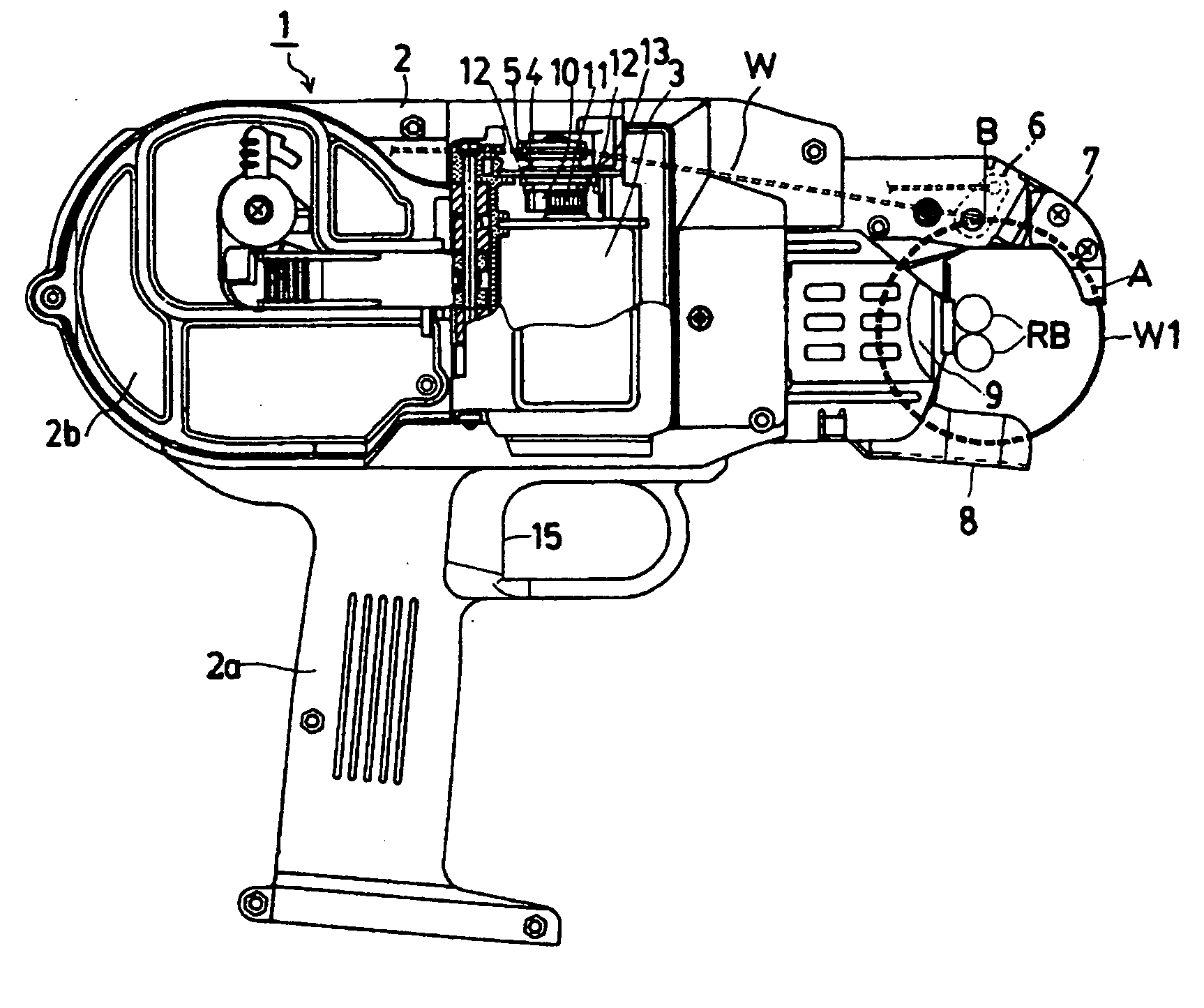
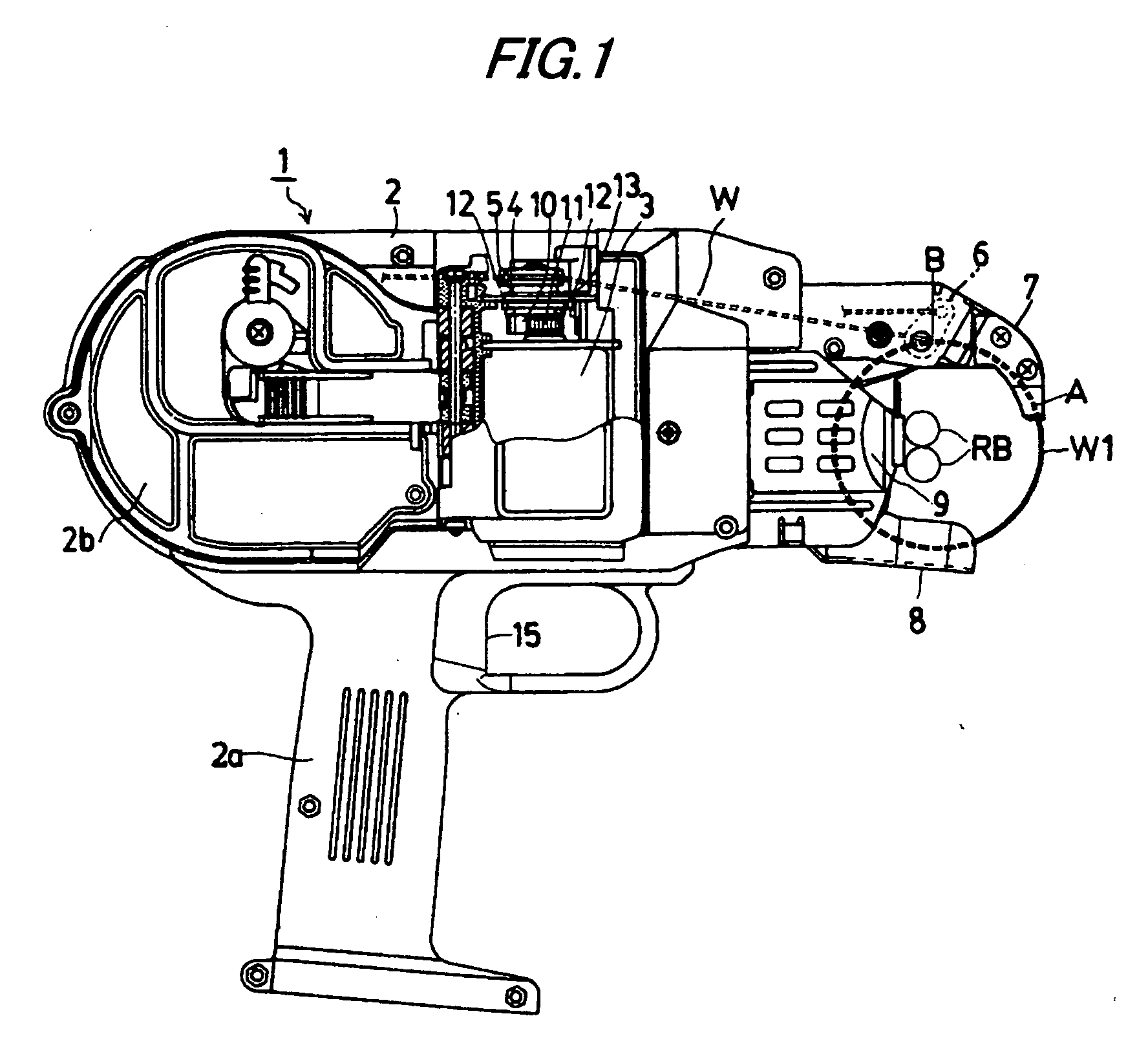
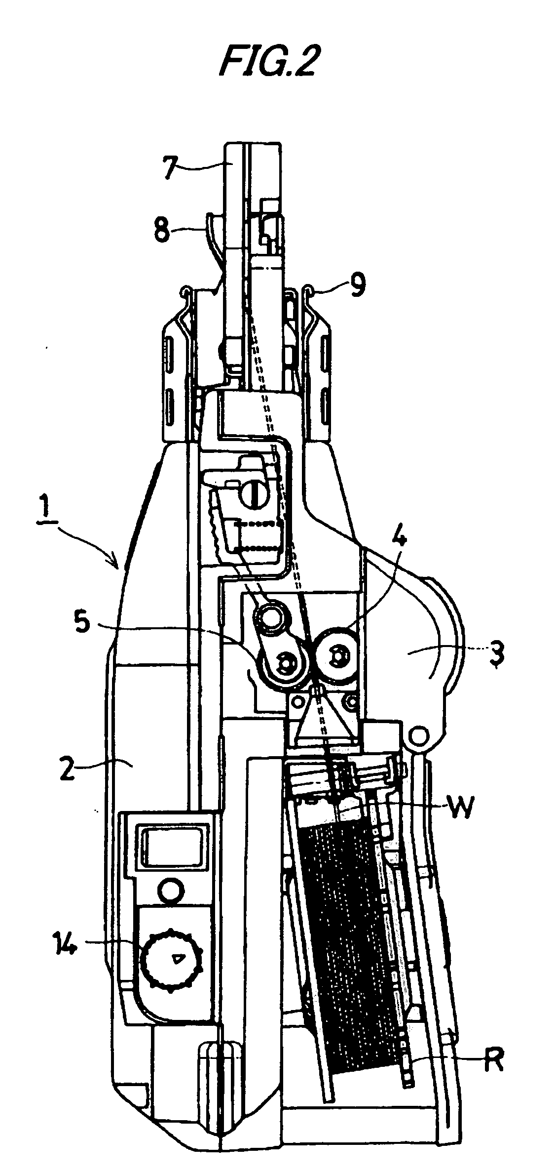
[0034]FIGS. 1 and 2 show a reinforcing bar binding machine 1. A wire reel receiving portion 2b is formed at a rear portion of a housing 2 having a grip portion 2a. A wire feed motor 3 is provided as a drive source. A wire feed mechanism is located forwardly of the wire reel receiving chamber 2b, and comprises a V-grooved drive gear 4 which is provided as a wire feed member, and is driven by the wire feed motor 3, and a V-grooved driven gear 5 which is provided as the wire feed member, and is disposed in mesh with the V-grooved drive gear 4 in resiliently contacted relation thereto.

[0035] As shown in FIG. 2, a wire W wound around a wire reel R within the wire reel receiving chamber 2b is gripped by the V-grooved drive gear 4 and the V-grooved driven gear 5, and is fed forward, and passes a rotary wire cutter 6 (shown in FIG. 1) serving as a wire cutting mechanism, and is fed to be curved in a generally arc-shape along a wire guide nose 7 of a curved shape to form a wire loop W1.

[00...


PUM

PropertyMeasurementUnit
Torqueaaaaaaaaaa

Abstract

A wire feed amount detection mechanism is configured by magnets mounted at an outer peripheral surface of a V-grooved drive gear of a wire feed mechanism and a magnetic sensor mounted on a body. A reinforcing bar winding turn number-setting switch is provided on the body. A control portion controls a wire feed amount of a wire feed mechanism based on a set value of the reinforcing bar winding turn number-setting switch. The number of turns of the wire around reinforcing bars can be arbitrarily set, for example, to any one of 1 to 4, and the binding can be effected with a binding force corresponding to a strength required by binding portions. As a result, with respect to those binding portions requiring a low binding force, the binding is effected with a smaller turn number, so that the amount of consumption of the wire can be saved, and besides those pipes (such as electric wiring pipes and hot water pipes) which are lower in strength than the reinforcing bars can also be bound together.

Description

TECHNICAL FIELD [0001] This invention relates to a reinforcing bar binding machine, and more particularly to a reinforcing bar binding machine in which a number of turns of a wire to be wound around reinforcing bars can be set arbitrarily. BACKGROUND ART [0002] As labor-saving means for a reinforcing bar binding work, there is an electrically-driven reinforcing bar binding machine for winding a wire around reinforcing bars to bind these reinforcing bars together. One kind of reinforcing bar binding machine is provided with a wire feed mechanism, a wire cutting mechanism, and a wire twisting mechanism, and a wire is fed along a guide nose of a curved shape by the wire feed mechanism, so that reinforcing bars are surrounded by a wire loop, and the wire loop is cut off from the wire extending from a trailing end of the wire loop by the wire cutting mechanism, and at the same time the wire loop is twisted by the wire twisting mechanism to bind the reinforcing bars in closely contacted r...

Claims


Application Information

Patent Timeline
IPC IPC(8): B21F45/00
CPCE04G21/122B65B13/025E04G21/123
Inventor ITAGAKI, OSAMU
Owner MAX CO LTD
Why Eureka
Try Eureka