
Image reading apparatus

a technology of image reading and reading device, which is applied in the direction of electrical equipment, picture communication, etc., can solve the problems of floating foreign matter, image noise, image noise, etc., and achieve the effect of preventing noise stripes from appearing

Active Publication Date: 2007-08-30
KONICA MINOLTA BUSINESS TECH INC
View PDF0 Cites 17 Cited by
  • Summary
  • Abstract
  • Description
  • Claims
  • Application Information

AI Technical Summary

Benefits of technology

[0012]An object of the present invention is to provide a sheet-through type image reading apparatus wherein adherence of sticky foreign matters to a transparent member for reading an image of a traveling document is prevented, wherein floating foreign matters can be removed and wherein noise stripes are prevented from appearing on a reproduced image.
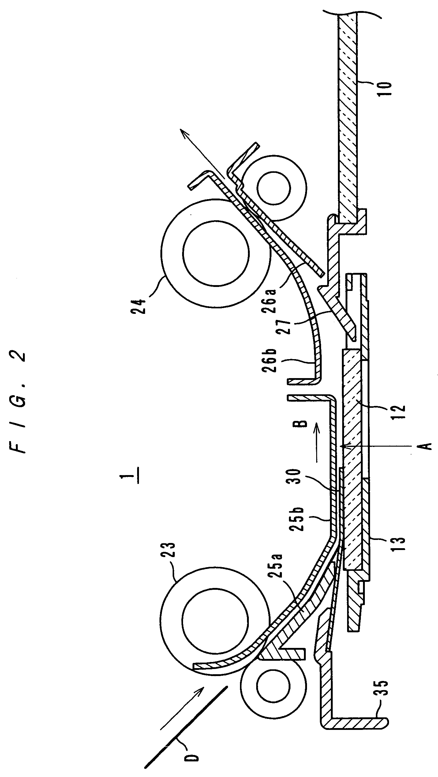
[0014]In the image reading apparatus according to the present invention, a document travels over the transparent member while being out of contact with the transparent member due to the document guide member. Thereby, it can be prevented that sticky foreign matters are transferred from the document to the transparent member. Further, either the transparent member or the document guide member is reciprocated substantially in parallel to the document feeding direction by a distance x2 larger than the distance x1 between the downstream edge of the document guide member and the reading position, so that foreign matters deposited on the reading position can be removed therefrom. Thus, there is no fear that striped noise may appear on a reproduced image.
[0015]In the image reading apparatus, the transparent member and the document guide member are in contact with each other at least from a time when the travel distance x2 becomes equal to x1 to a time when a forward movement by the distance x2 completes. In other words, the transparent member and the document guide member come into contact with each other at the latest when the downstream edge of the document guide member reaches the reading position and keep in contact with each other until a forward movement by the distance x2 completes, so that the downstream edge of the document guide member can push foreign matters deposited on the reading position away therefrom. Alternatively, if the downstream edge of the document guide member is at a distance x3 from a downstream edge with respect to the document feeding direction of the transparent member, the distances x2 and x3 may be in relationship of x2≧x3. In this case, foreign matters deposited on the reading position can be removed completely from the transparent member.

Problems solved by technology

These sticky foreign matters do not come off the reading glass easily and cause image noise.
Also, floating matters, such as paper rubbish dispersed from documents and dust in the air, are deposited on the reading glass, which causes image noise.
In the non-contact method, the trailing portion of a traveling document comes into contact with the reading glass because the trailing portion is no longer supported after having passed the step, and floating foreign matters may be dragged into the trailing portion of the document and may be ejected.
In the non-contact method, however, the trailing portion of the document which comes into contact with the reading glass is a small area, and it is difficult to certainly remove floating foreign matters from the periphery of the reading glass.
In this structure, troublesome maintenance (changes and cleaning) of the catcher member is necessary.
Also, the catcher member cannot be located at the reading position, and it is impossible to catch dust which has fallen onto the reading position.
Therefore, in images formed by the monochromatic reading apparatus, image noise due to very small floating foreign matters such as paper dust is not very apparent.
Therefore, very small floating foreign matters, which do not become apparent in the monochromatic reading apparatus, are also read, and consequently, noise appears on a reproduced image as narrow stripes.

Method used


Image

  • Image reading apparatus
  • Image reading apparatus
  • Image reading apparatus

Examples


Embodiment Construction

[0041]Embodiments of an image reading apparatus according to the present invention are described with reference to the accompanying drawings. In the embodiments below, same parts and same members are referenced with same reference marks, and repeated descriptions are omitted.

Image Reading Apparatus; See FIGS. 1-6

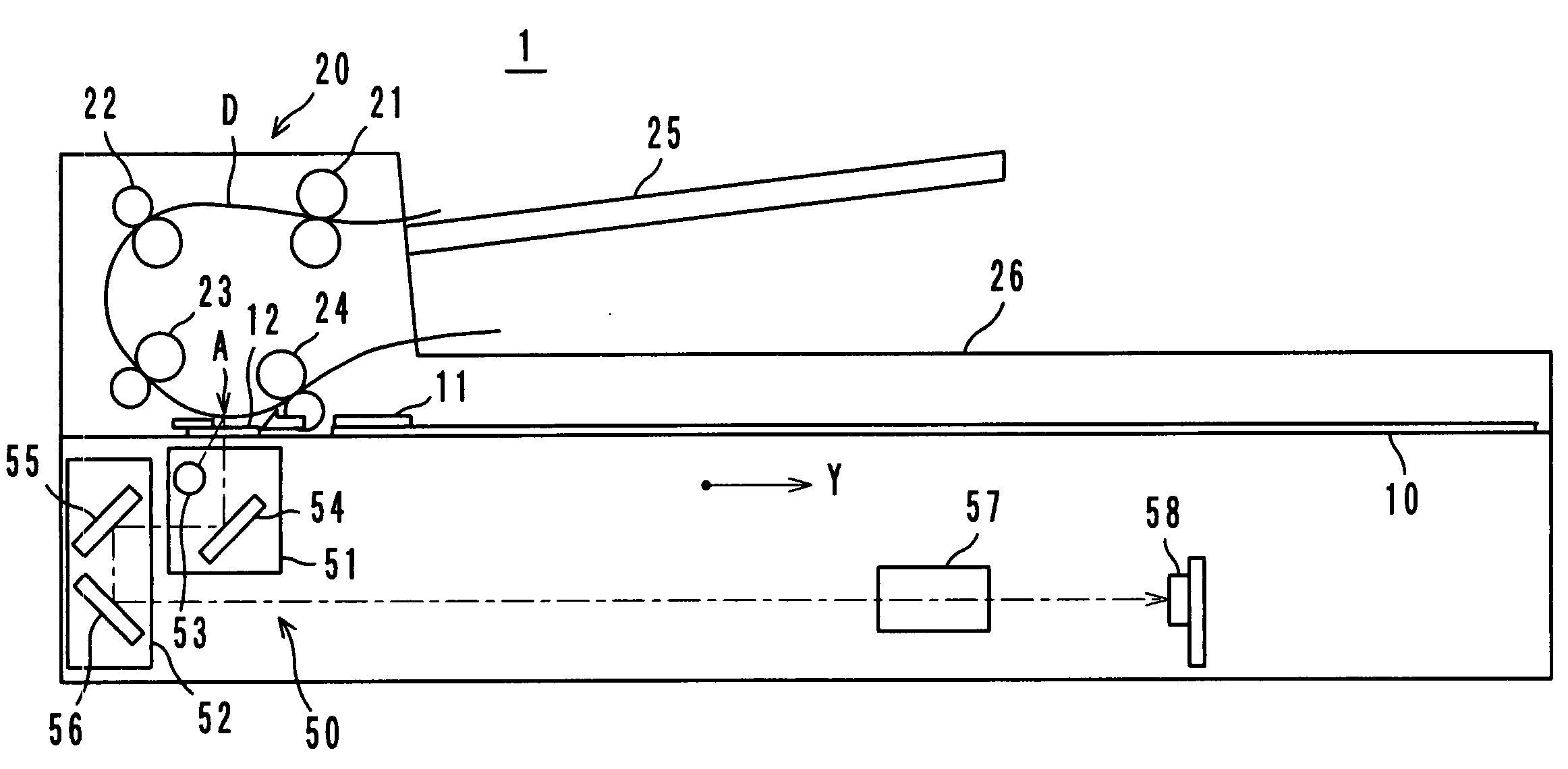
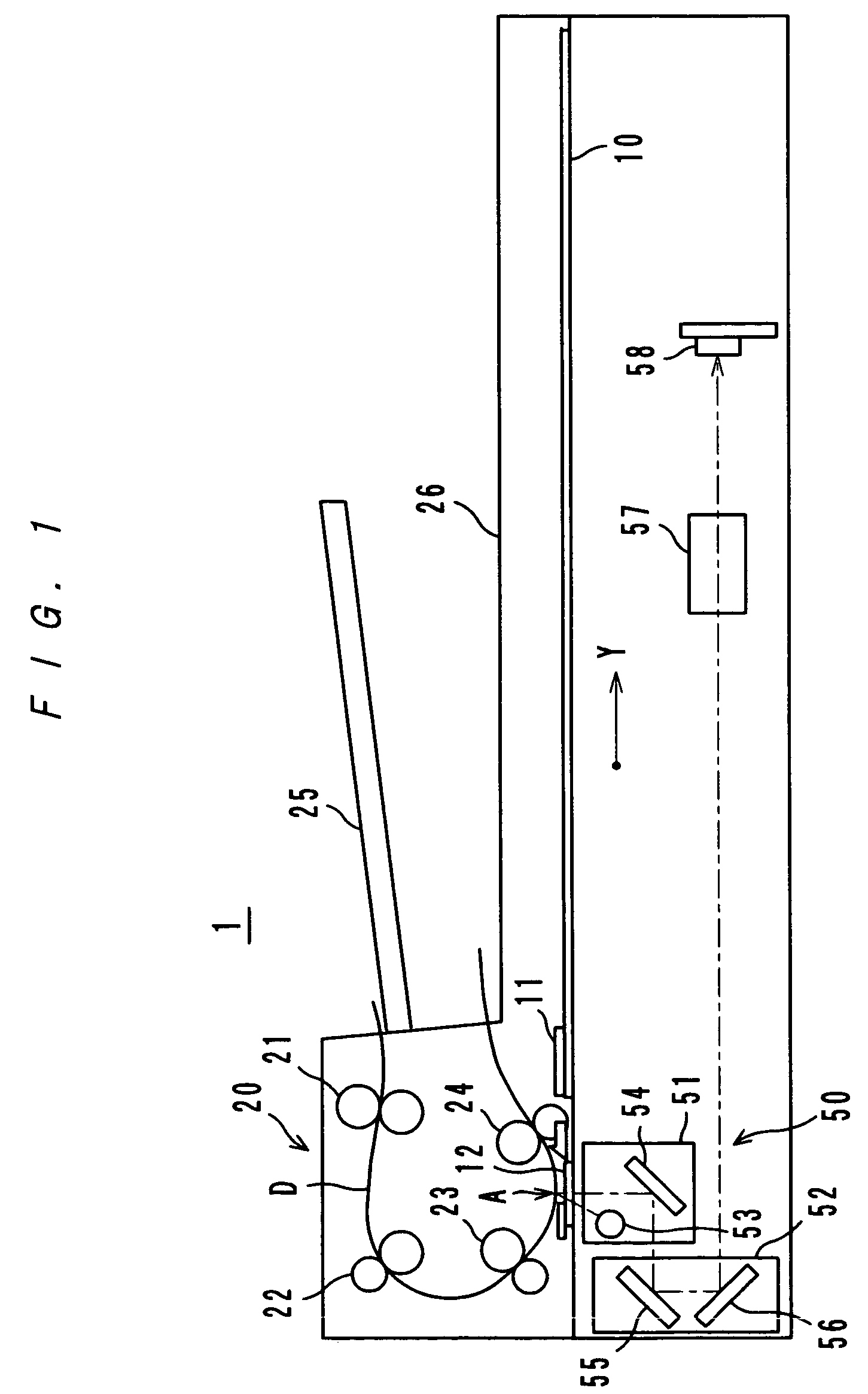
[0042]FIG. 1 shows an image reading apparatus 1 according to an embodiment of the present invention. The image reading apparatus 1 adopts both a platen-set method wherein an image of a document (not shown) set on a platen glass 10 is read and a sheet-through method wherein an image of a document D fed by an automatic document feeder 20 is read, and an image reading optical system (a scanner) 50 is provided.

[0043]Image reading by the platen-set method is carried out as follows: a document set on the platen glass 10 is irradiated by a lamp 53, for example, a rare gas fluorescent lamp; light reflected by the document is further reflected by mirrors 54, 55 and 56, and then enter...


PUM


Abstract

An image reading apparatus which reads a document image optically at a reading position while feeding the document over a reading glass. A document guide sheet for forming a step so as to prevent an imaged surface of a fed document from coming into contact with the reading glass is provided at an upstream side of the reading position with respect to a document feeding direction. The reading glass is capable of reciprocating in the document feeding direction by a specified distance x2. If the document guide sheet is located such that a downstream edge of the document guide sheet is at a distance x1 from the reading position, the distances x1 and x2 are in relationship of x1<x2.

Description

[0001]This application is based on Japanese Patent Applications No. 2006-051228 and No. 2006-051229 filed on Feb. 27, 2006, the contents of which are incorporated herewith by reference.BACKGROUND OF THE INVENTION[0002]1. Field of the Invention[0003]The present invention relates to an image reading apparatus, and more particularly to a document feeding type image reading apparatus which is suited to be used as an image input device for a copying machine and a scanner.[0004]2. Description of Related Art[0005]In the art of image reading apparatuses for reading images optically, a platen-set method wherein an image of a document set on a platen glass is read and a sheet-through method wherein an image of a document is read while the document is being fed are adopted separately or at the same time. The sheet-through method is advantageous in its small size, low cost, low noise, high-speed image reading and high printing efficiency. Therefore, the sheet-through method is generally adopted...

Claims


Application Information

Patent Timeline
Patent Type & Authority Applications(United States)
IPC IPC(8): H04N1/04
CPCH04N1/0057H04N1/00588H04N1/00909H04N1/00602H04N1/00604H04N1/00591
Inventor NISHIKAWA, HIROSHIMARUCHI, NORITOSHI
Owner KONICA MINOLTA BUSINESS TECH INC
Learn More