Multi-core optical fiber and method of making and using same

Inactive Publication Date: 2007-08-30
NAVY USA AS REPRESENTED BY THE SEC THE
View PDF59 Cites 116 Cited by
  • Summary
  • Abstract
  • Description
  • Claims
  • Application Information

AI Technical Summary

Problems solved by technology

Several prior methods employing optical fibers to sense bending are not discussed in depth here because of their intrinsic limits of sensitivity and specificity, or where few of these devices could be operated serially in a single fiber optic core.

Method used


Image

  • Multi-core optical fiber and method of making and using same
  • Multi-core optical fiber and method of making and using same
  • Multi-core optical fiber and method of making and using same

Examples


Embodiment Construction

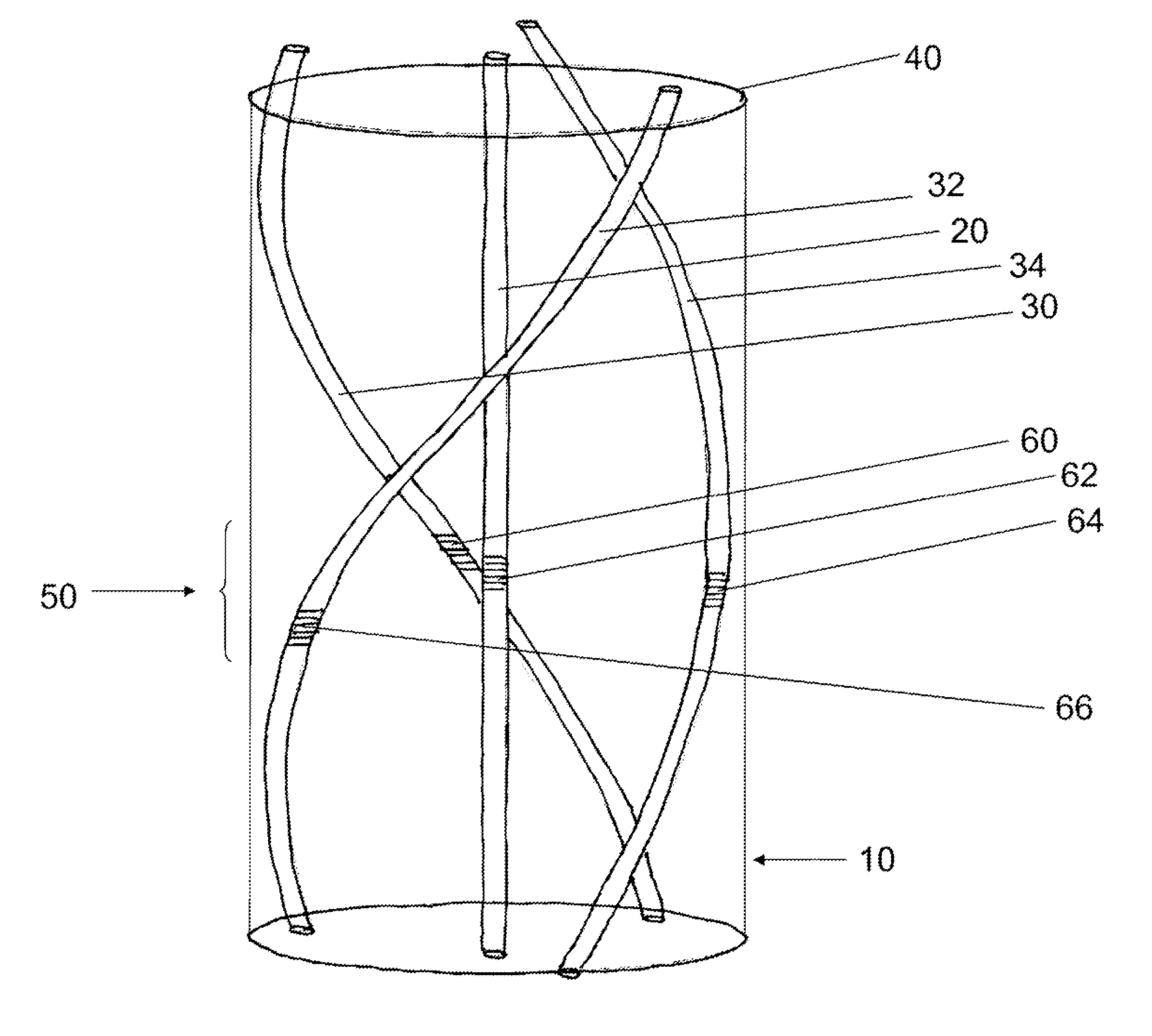
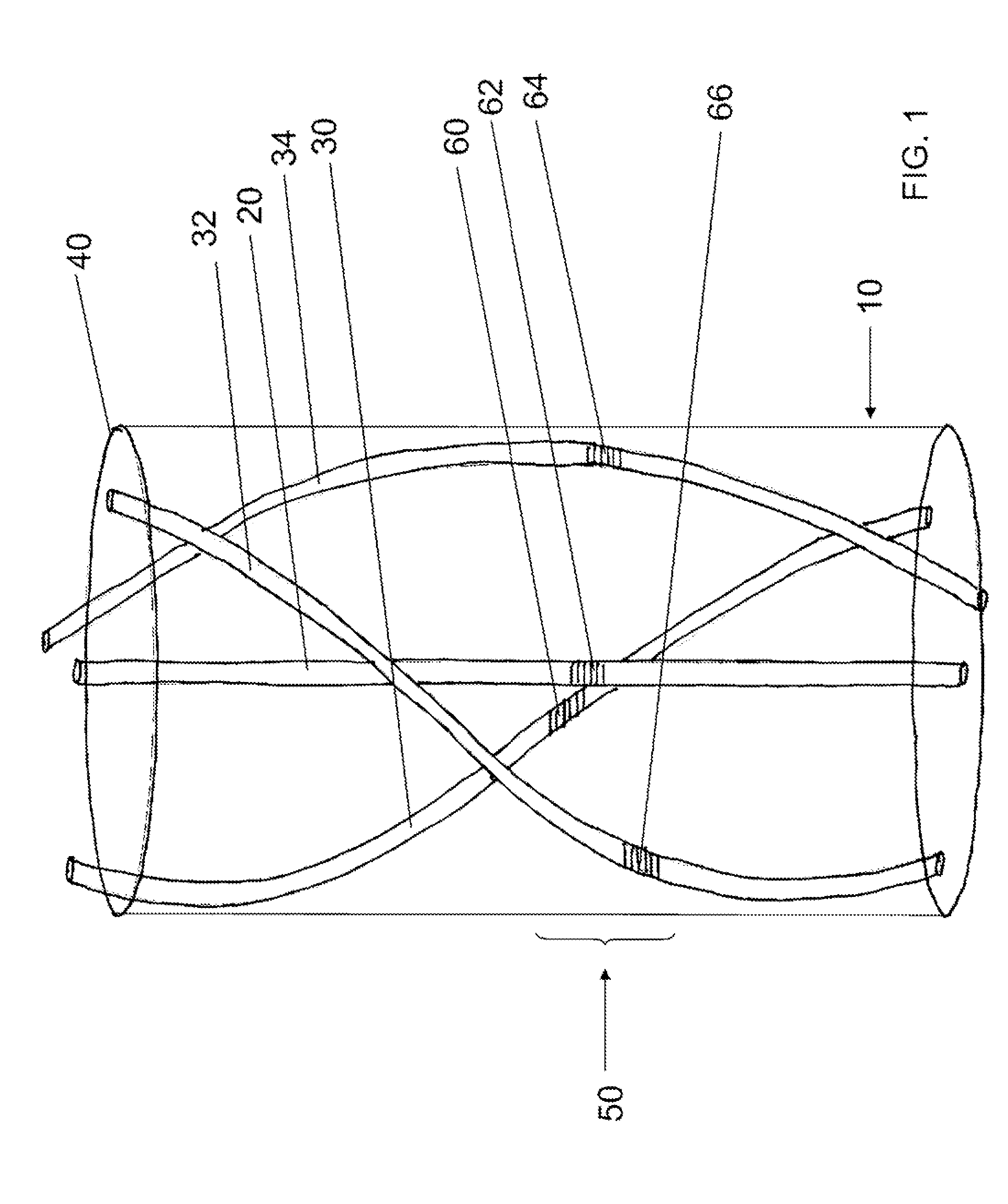
[0017] An embodiment of the invention includes an apparatus, shown by way of example in FIG. 1. The apparatus includes a fiber 10 comprising an axial center, a central single-mode waveguiding core 20 and a plurality of peripheral single-mode waveguiding cores 30, 32, 34. The central single mode core 20 is located at a first distance from the axial center. The plurality of peripheral cores 30, 32, 34 is located at respective second distances from the axial center. Each of the respective second distances is greater than the first distance, and each peripheral core of the plurality of peripheral cores 30, 32, 34 follows a respective first helix about the axial center.

[0018] Optionally, the central core 20 is located coincident with said axial center. Optionally, the fiber comprises an optical surface 40, the plurality of peripheral cores is located at respective third distances from the optical surface 40. Optionally, each of the respective third distances is greater than a diameter o...


PUM

PropertyMeasurementUnit
pitch lengthaaaaaaaaaa
line-width aaaaaaaaaa
center Bragg wavelengthaaaaaaaaaa

Abstract

The apparatus includes a fiber comprising an axial center, a central single-mode waveguiding core and a plurality of peripheral single-mode waveguiding cores. The central core is located at a first distance from the axial center. The plurality of peripheral cores is located at respective second distances from the axial center. Each of the respective second distances is greater than the first distance, and each peripheral core of the plurality of peripheral cores follows a respective first helix about the axial center. The central core and the plurality of peripheral cores include an optical strain sensor rosette.

Description

TECHNICAL ART [0001] The invention relates generally to optical fibers, and more specifically to multi-core optical fibers for use in measuring twist, bend, and / or temperature. BACKGROUND ART [0002] Many applications involving long, narrow and flexible structures (e.g., cables, tethers, etc.) would gain by knowing the 3-dimensional shape of those structures as they are deflected. For structures that have large cross-sections compared with those typical of optical fiber, shape monitoring has been proposed through the attachment of multiple, one-dimensional fiber-optic strain-sensing arrays, for example, as disclosed in U.S. Pat. No. 6,728,431 to Ames, incorporated herein by reference. [0003] Several prior methods employing optical fibers to sense bending are not discussed in depth here because of their intrinsic limits of sensitivity and specificity, or where few of these devices could be operated serially in a single fiber optic core. Examples would include sensors based on bend-ind...

Claims


Application Information

Patent Timeline
Patent Type & Authority Applications(United States)
IPC IPC(8): G02B6/34G02B6/00G02F1/295
CPCG02B6/02042G01B11/18
Inventor ASKINS, CHARLESFRIEBELE, JOSEPHMILLER, GARY A.
Owner NAVY USA AS REPRESENTED BY THE SEC THE
Why Eureka
Try Eureka