Pipe and tubing connector

a technology of connectors and tubing, applied in the direction of couplings, conveyors, rod connections, etc., can solve the problems of difficult installation, difficult two-piece design, and more expensive two-piece manufacturing, so as to achieve less manufacturing costs and facilitate installation.

Active Publication Date: 2007-09-06
R & B WAGNER
View PDF5 Cites 40 Cited by
  • Summary
  • Abstract
  • Description
  • Claims
  • Application Information

AI Technical Summary

Benefits of technology

[0008]The present invention has several advantages over the existing pipe and tubing connectors. Most significantly, the present invention provides a unitary expansion member that is less expensive to manufacture and easier to inst

Problems solved by technology

Although the prior art connector 10 works well as a connector or expansion joint, it also has drawbacks.
Most significantly, the two-piece design causes difficulties.
The two channel pieces 12, 14 are not secured together until at least one set s

Method used


Image

  • Pipe and tubing connector
  • Pipe and tubing connector
  • Pipe and tubing connector

Examples


Embodiment Construction

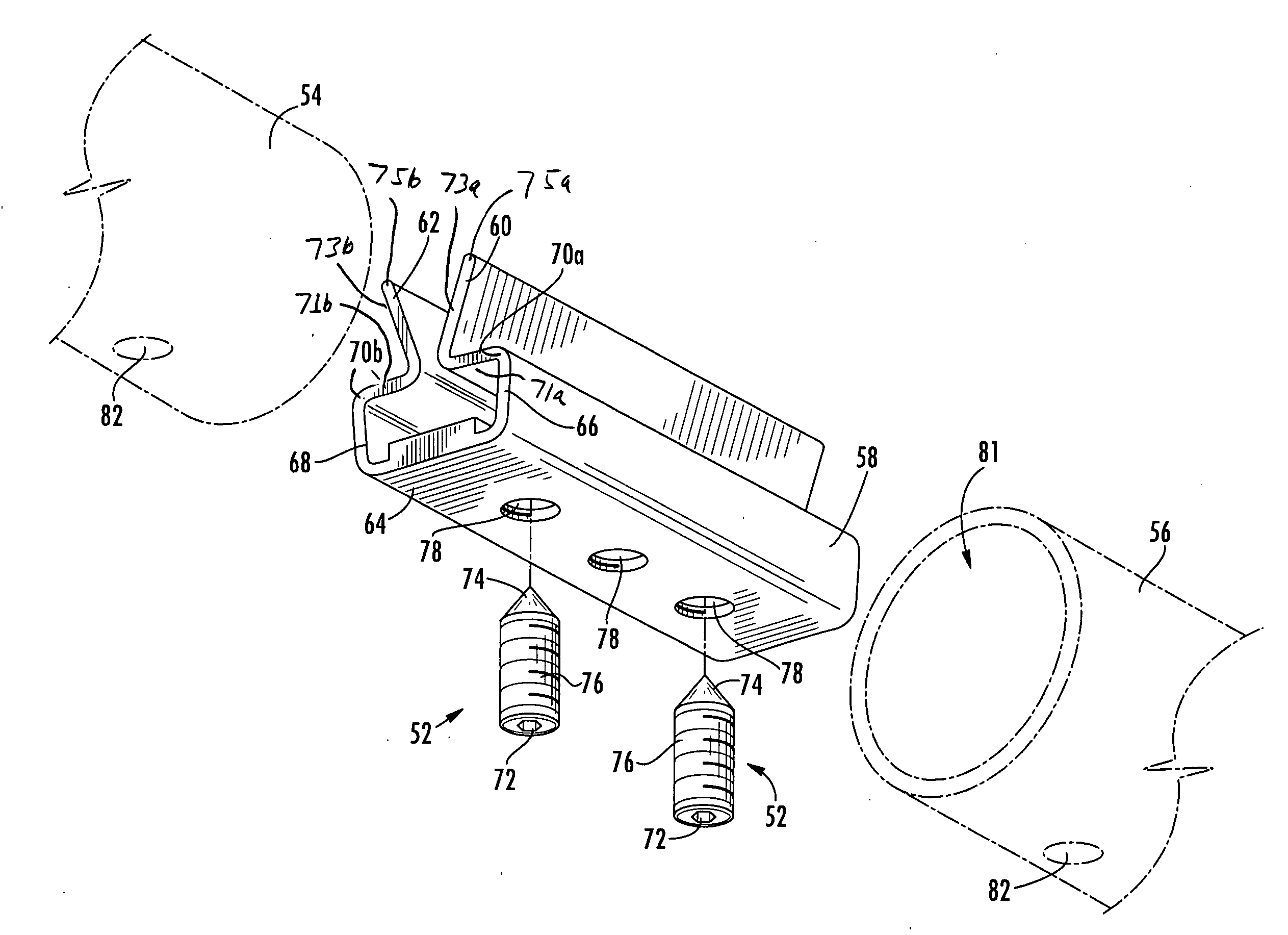
[0017]The present invention provides a connector for pipe or tubing that can be used for example to connect handrail sections and keep the connected sections in secure alignment. Referring now to FIGS. 4-8, the connector of the present invention includes a unitary expansion member 50 and is to be used with at least one fastener 52.

[0018]As shown in FIGS. 4-8, the unitary expansion member 50 is an extrusion, the length of which is determined at the time the member is put into use. In terms of cross section, as shown best in FIG. 6, member 50 has a body 58, a first expansion leg 60 and a second expansion leg 62. The body 58 is a generally flat member, oriented in a predetermined plane. The body 58 includes a thickened or boss portion 64, the purpose of which will be explained below. First expansion leg 60 includes a thigh portion 66 extending in a direction transverse to the plane of the body 58. First expansion leg 60 then has a bent or knee portion 70a, where it bends toward second ...


PUM


Abstract

A connector for pipe or tubing. The connector includes a unitary expansion member, formed from a body, a first expansion leg extending from the body, an optional second expansion leg extending from the body, and at least one opening extending through the body. In use, the connector is fastened in place by a fastener that is inserted through the at least one opening to contact at least one of the first and second expansion legs and force at least one of them to deform and contact the inside of the pipe or tubing, thereby securing the connector within the pipe or tubing.

Description

BACKGROUND OF THE INVENTION[0001]The present invention relates generally to connectors, and more particularly to a one-piece splice connector for use with pipe and tubing.[0002]Pipe and tubing connectors are well known in the art. One such connector, sold under the trademark SPLICE LOCK™ by R&B Wagner, Inc. of Milwaukee, Wis., that is particularly well suited for use in the alignment of handrail pipe and tubing sections and as expansion joints is disclosed in U.S. Pat. No. 3,484,830. An example of such a connector is also shown in FIGS. 1-3, and includes a pair of separate channel sections 12, 14 and at least one set screw 41. First channel section 12 includes side wall flanges 16, a pair of slots 22, and a threaded aperture 24. Second channel section 14 includes side wall flanges 26 and a pair of prongs 32. The side wall flanges 16, 26 are formed for mating engagement with one another, and prongs 32 extend into slots 22 when the connector is assembled. One or more screws 41 are use...

Claims


Application Information

Patent Timeline
IPC IPC(8): F16B12/36
CPCE04F11/1836F16B2/04F16B7/0413Y10T403/5741Y10T403/7176Y10T403/55Y10T403/557
Inventor WAGNER, ROBERTNASH, ALAN
Owner R & B WAGNER
Why Eureka
Try Eureka