Latch system

a technology of latching system and latching plate, which is applied in the direction of passenger lock actuation, lock application, mechanical apparatus, etc., can solve the problems of b>8/b> being awkward for an occupant of the vehicle, unable to unlock the vehicle, and unable to drain the battery of the vehicle, etc., and achieve the effect of ensuring the door is opened

Inactive Publication Date: 2008-12-11
INTEVA PRODUCTS LLC
View PDF2 Cites 44 Cited by
  • Summary
  • Abstract
  • Description
  • Claims
  • Application Information

AI Technical Summary

Benefits of technology

[0008]The present invention provides a system whereby an occupant of a vehicle can lock the door latches of the vehicle while remaining in the vehicle while the vehicle engine is turned off, but can readily open the door when required.
[0011]The present invention provides a latch system which is less expensive to manufacture and produce.
[0014]The present invention provides a latch system which is less expensive to manufacture and produce.

Problems solved by technology

However, there are occasions when a driver or other vehicle occupant may wish to remain in the vehicle (perhaps while taking a rest on a long journey), but nevertheless have the vehicle doors locked.
Under these circumstances, the vehicle engine will not be running and hence locking the vehicle using the electromagnet 7 would potentially drain the vehicle's battery.
On the other hand, if the vehicle is locked by using the permanent magnet 8 and then an electrical failure occurred, it is not possible to unlock the vehicle using the electromagnet 7 to move the permanent magnet 8.
Using a key to move the permanent magnet 8 would be awkward for an occupant of the vehicle since the key hole would be on the outside of the vehicle.

Method used


Image

  • Latch system
  • Latch system
  • Latch system

Examples


Embodiment Construction

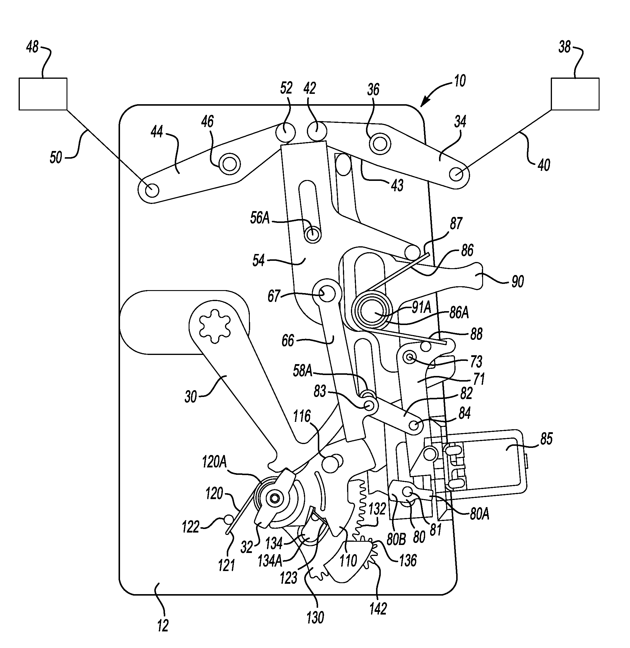
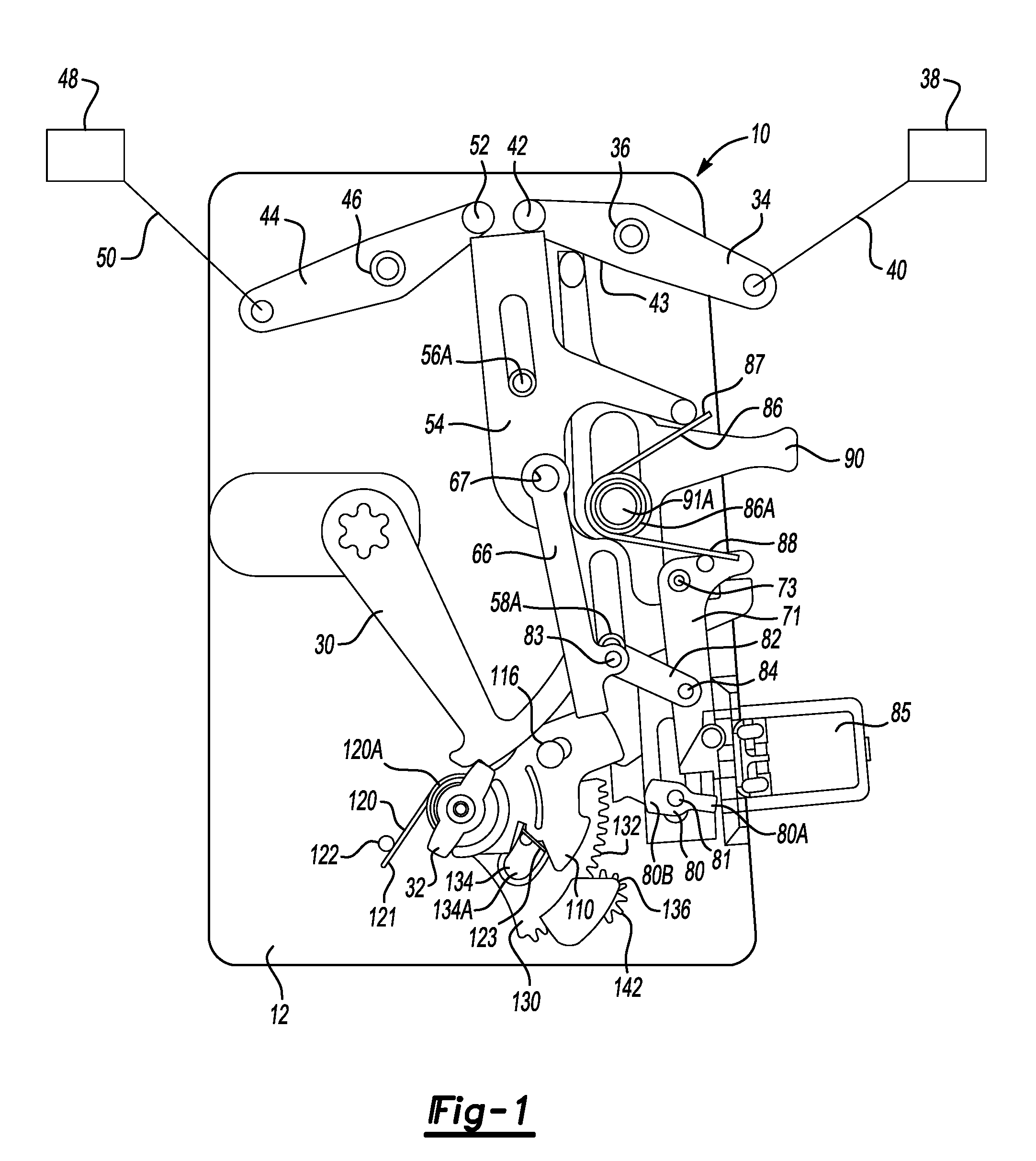
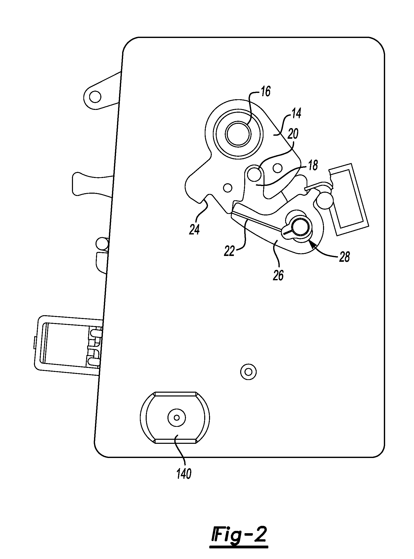
[0023]With reference to FIG. 1, there is shown a latch 10 having a latch chassis 12 upon which various components of the latch 10 are mounted. A latch bolt in the form of a rotating claw 14 is pivotally mounted about a pivot pin 16 on the latch chassis 12, as shown in FIG. 2. The rotating claw 14 includes a mouth 18 for releasably retaining a striker 20. The claw 14 includes a closed abutment 22 and a first safety abutment 24. A pawl 26 engages the closed abutment 22 to hold the claw 14 in a closed position. Alternatively, the pawl 26 can engage the first safety abutment 24 to hold the claw 14 in a first safety position. In this position, while the latch 10 is not fully closed, nevertheless the door will not open. By disengaging the pawl 26 from the claw 14, the claw 14 is free to rotate to an open position, thereby releasing the striker 20 and allowing the associated door (typically attached to the latch) to open. The pawl 26 is mounted on an eccentric arrangement 28, details of wh...


PUM


Abstract

A latch system includes a latch bolt, a pawl for releasably retaining the latch bolt in a closed position, a first release member, a first transmission path connecting the first release member to the pawl, a second release member, and a second transmission path connecting the second release member to the pawl. A portion of the first transmission path and a portion of the second transmission path have a common portion, the common portion including a lock link having a first position at which the lock link completes the first transmission path and the second transmission path such that operation of either the first release member or the second release member opens a latch, and the lock link having a second position at which the lock link breaks the first transmission path and the second transmission path such that a single operation of either the first release member or the second release member does not open the latch. The latch system includes a first device capable of holding the lock link in the second position, a second device capable of holding the lock link in the second position, and a third device capable of holding the lock link in the second position.

Description

REFERENCE TO RELATED APPLICATIONS[0001]This application claims priority to United Kingdom Patent Application No. GB 0711027.3 filed on Jun. 8, 2007.BACKGROUND OF THE INVENTION[0002]The present invention relates to a latch system, in a particular a latch system for a vehicle door, such as a car door.[0003]European patent application EP01310100 shows a known latch arrangement (see FIG. 20 of the present case). The latch arrangement includes a latch chassis 1 on which is rotatably mounted a lever 2 which operates a link 3, which in turn moves a pin 4 to release the latch. Movement of the link 3 is controlled by a lever 5 and a link 6. The position of the lever 5 is controlled either by an electromagnet 7 or by a permanent magnet 8. Springs 9A and 9B control the position of various components during operation.[0004]One of the embodiments shown in European patent application EP01310124 shows a similar arrangement.[0005]In both cases, the lever 5 can be prevented from moving in one of two...

Claims


Application Information

Patent Timeline
Patent Type & Authority Applications(United States)
IPC IPC(8): E05C3/16
CPCE05B47/0038E05B77/30E05B81/36E05B81/14E05B81/16E05B81/06Y10T292/1047Y10T292/1082E05B47/0676
Inventor SPURR, NIGEL V.
Owner INTEVA PRODUCTS LLC
Why Eureka
Try Eureka