System to detect the presence of a queen bee in a hive

a technology of a system and a bee, which is applied in the field of systems to detect the presence of queen bees, can solve the problems of laborious, difficult to find 1 in 60,000 queen bees, and time-consuming and labor-intensive problems of finding queen bees in each hiv

Inactive Publication Date: 2007-09-06
BERRY JENNIFER
View PDF5 Cites 20 Cited by
  • Summary
  • Abstract
  • Description
  • Claims
  • Application Information

AI Technical Summary

Benefits of technology

[0013]In the broadest and simplest sense, the invention comprises several embodiments, namely: 1) an RFID tag secured to the queen, a detector positioned near the opening of the hive that detects the presence of the RFID tag when the queen passes through the opening, and a signal device (like an LED) to indicate if the queen has left the hive or is in the hive; 2) another embodiment comprises a bit of metal secured to the queen, a metal detector positioned near the opening of the hive that detects the presence of the metal on the queen when she passes through the opening, and a signal device to indicate if the queen has left the hive or is in the hive; and 3) another embodiment comprises one or more infrared cameras positioned adjacent the hive entrance, coupled with computer identification scanning software that can detect the difference between a drone, a worker and a queen bee, and a signal device to indicate if the queen has left the hive or is in the hive.
[0014]In the broadest sense, the invention also comprises an RFID tag/bit of metal secured to the queen, a detector near the opening of the hive that detects the presence of the RFID tag/bit of metal when it is near the hive opening, and an output signal device to pick-up from the detector the presence of the RFID tag/bit of metal, the signal device which may be a simple LED to indicate if the queen has left the hive or is in the hive. Optionally, the invention may include an antenna to remotely send the detector output signal to a receiver, and the receiver to indicate if the queen has left the hive or is in the hive

Problems solved by technology

Therefore, when it is time to find the queen, it can be very difficult to find 1 in 60,000.
Trying to either determine if the queen is in the hive or find the queen

Method used


Image

  • System to detect the presence of a queen bee in a hive
  • System to detect the presence of a queen bee in a hive
  • System to detect the presence of a queen bee in a hive

Examples


Embodiment Construction

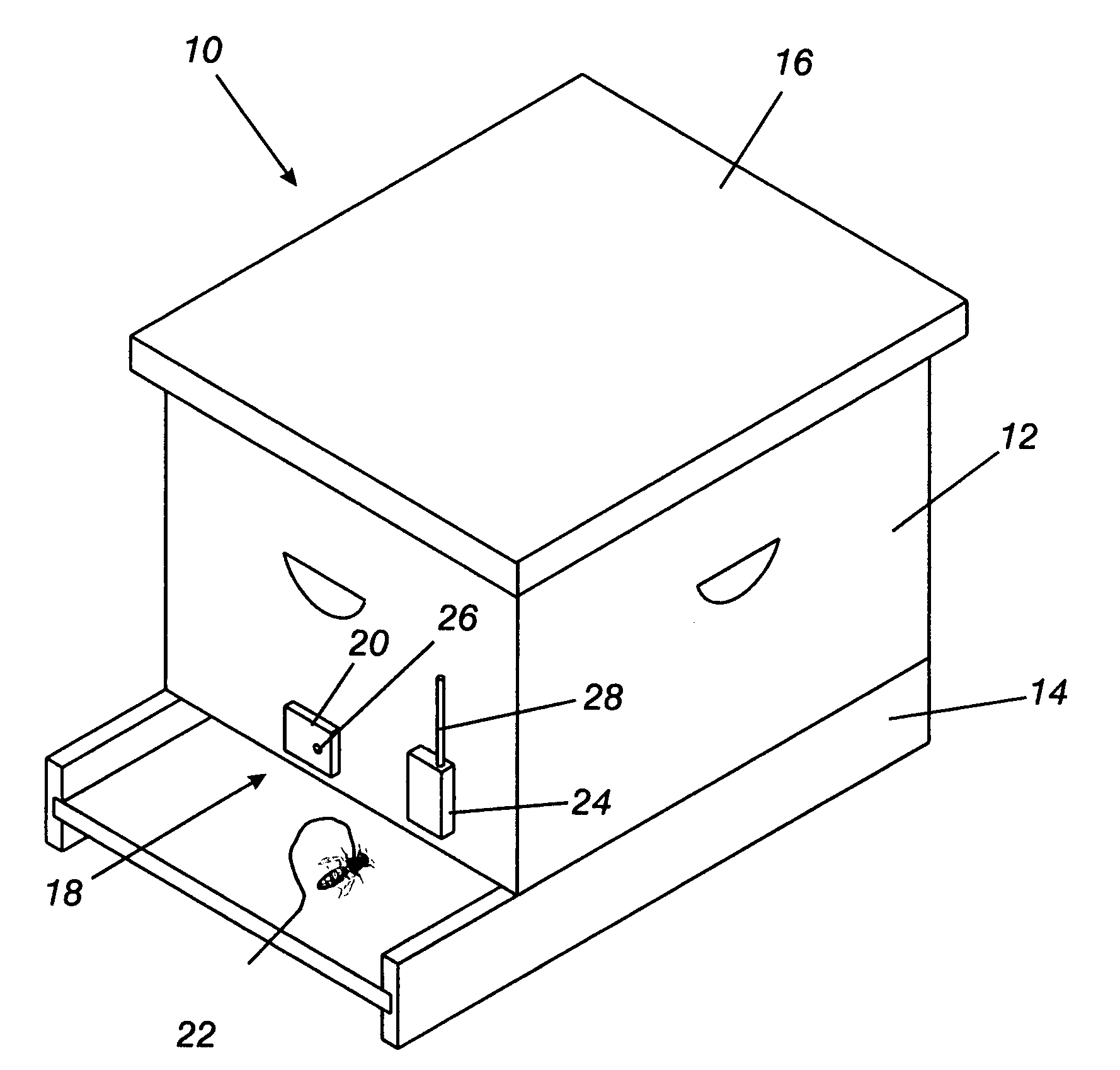
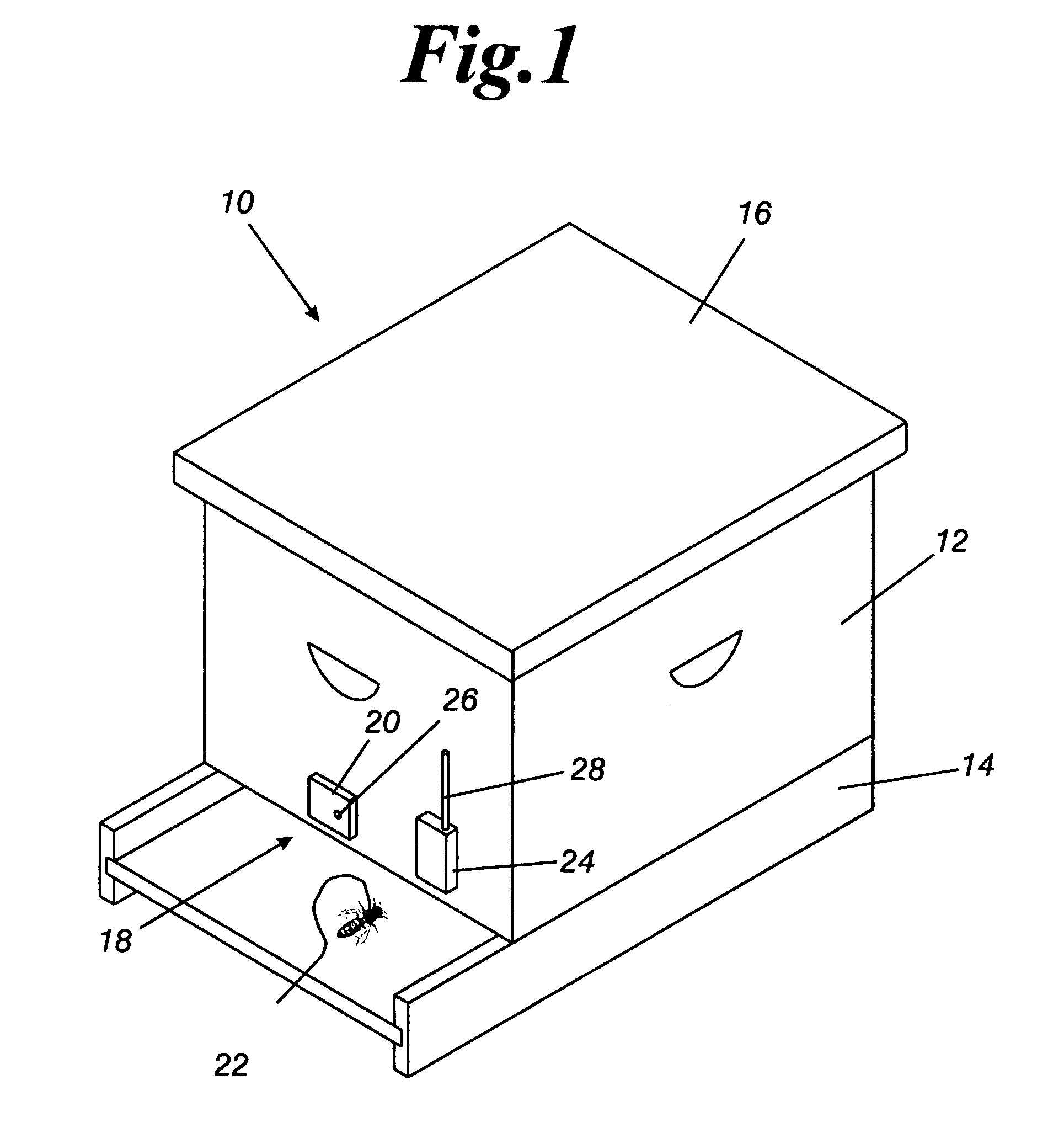
[0026]Beehives are well known and their construction and materials employed form no part of the present invention. As illustrated in FIG. 1, a beehive 10 comprises a hive body 12 that typically sits on a base 14 that is longer than the have body so as to form a platform for the bees to land and take-off. An opening 18 provides ingress and egress to the hive. Lastly, the hive body is covered with a weather resistant cover 16.

[0027]RFID tags are well known. A queen bee is shown on the platform and has an RFID tag 22 secured to her thorax by an adhesive. Likewise, RFID detectors 20 are also well known. The RFID detector 20 is capable of detecting any bee that has an RFID tag secured to it. While the RFID detector 20 is shown as being smaller than the opening, it is within the scope of the invention to make it substantially as long as the opening 18 to improve its efficiency in detecting the queen. The detector includes a power source, such as batteries, not shown, to power the detector...


PUM


Abstract

The present invention is a system to detect the presence of a queen bee, in a hive. The first system includes an RFID (radio frequency identification) tag (secured to the queen) and a RFID detection device secured adjacent the hive opening that sends an output that indicates the presence or absence of the queen bee. In a second embodiment, a bit of metal (thin foil) can be secured to the queen by means of an adhesive, and a metal detector can be positioned by the hive opening to detect the metal, and send an output that indicates the presence or absence of the queen bee. In a third embodiment, one or more infrared cameras can be positioned adjacent the hive entrance, coupled with detection scanning software that can detect the difference between a drone, a worker and a queen bee, and indicate the presence or absence of the queen bee.

Description

[0001]This patent application claims the benefit of applicant's provisional patent application filed Mar. 1, 2006, under Ser. No. 60 / 777,856.BACKGROUND OF THE INVENTION[0002]1) Field of the Invention[0003]The present invention is a system to detect the presence of a queen bee, particularly a queen honeybee, in a hive. Different alternative forms of the invention are disclosed. The first system includes an RFID (radio frequency identification) tag (secured to the queen) and a detection device that detects the RFID tag (secured to the hive opening, for example) and sends or records an output that can be interpreted as indicating the presence or absence of the queen bee. Alternatively, in a second embodiment of the present invention, a bit of metal (thin foil) can be secured to the queen by means of an adhesive, for example, and a metal detector can be positioned by the hive opening to detect the metal, and send or record an output that can be interpreted as indicating the presence or ...

Claims


Application Information

Patent Timeline
IPC IPC(8): A01K47/00
CPCA01K11/006A01K49/00A01K47/06
Inventor BERRY, JENNIFER
Owner BERRY JENNIFER
Why Eureka
Try Eureka