Flexible stent

a flexible, stent technology, applied in the field of expandable tubular structures, can solve the problems of stent failure, axial compression and repeated displacement, and stent may be subject to substantial flexing or bending,

Active Publication Date: 2007-09-06
FLEXIBLE STENTING SOLUTIONS
View PDF14 Cites 59 Cited by
  • Summary
  • Abstract
  • Description
  • Claims
  • Application Information

AI Technical Summary

Problems solved by technology

Yet, after deployment, in certain applications, a stent may be subjected to substantial flexing or bending, axial compressions and repeated displacements at points along its length, for example, when stenting the superficial femoral artery.
This can produce severe strain and fatigue, resulting in failure of the stent.
A similar problem exists with respect to stent-like structures.

Method used


Image

  • Flexible stent
  • Flexible stent
  • Flexible stent

Examples


first embodiment

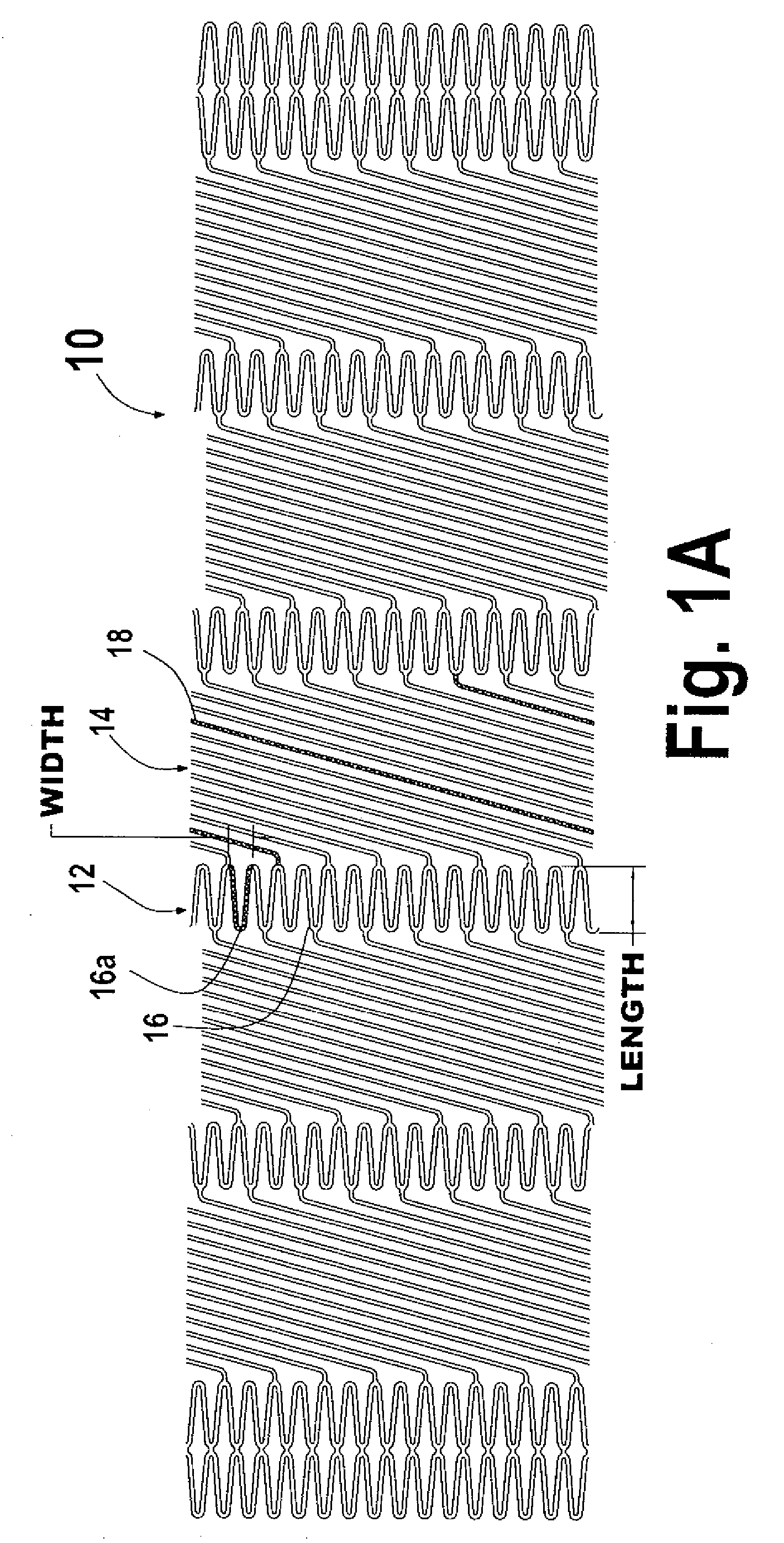
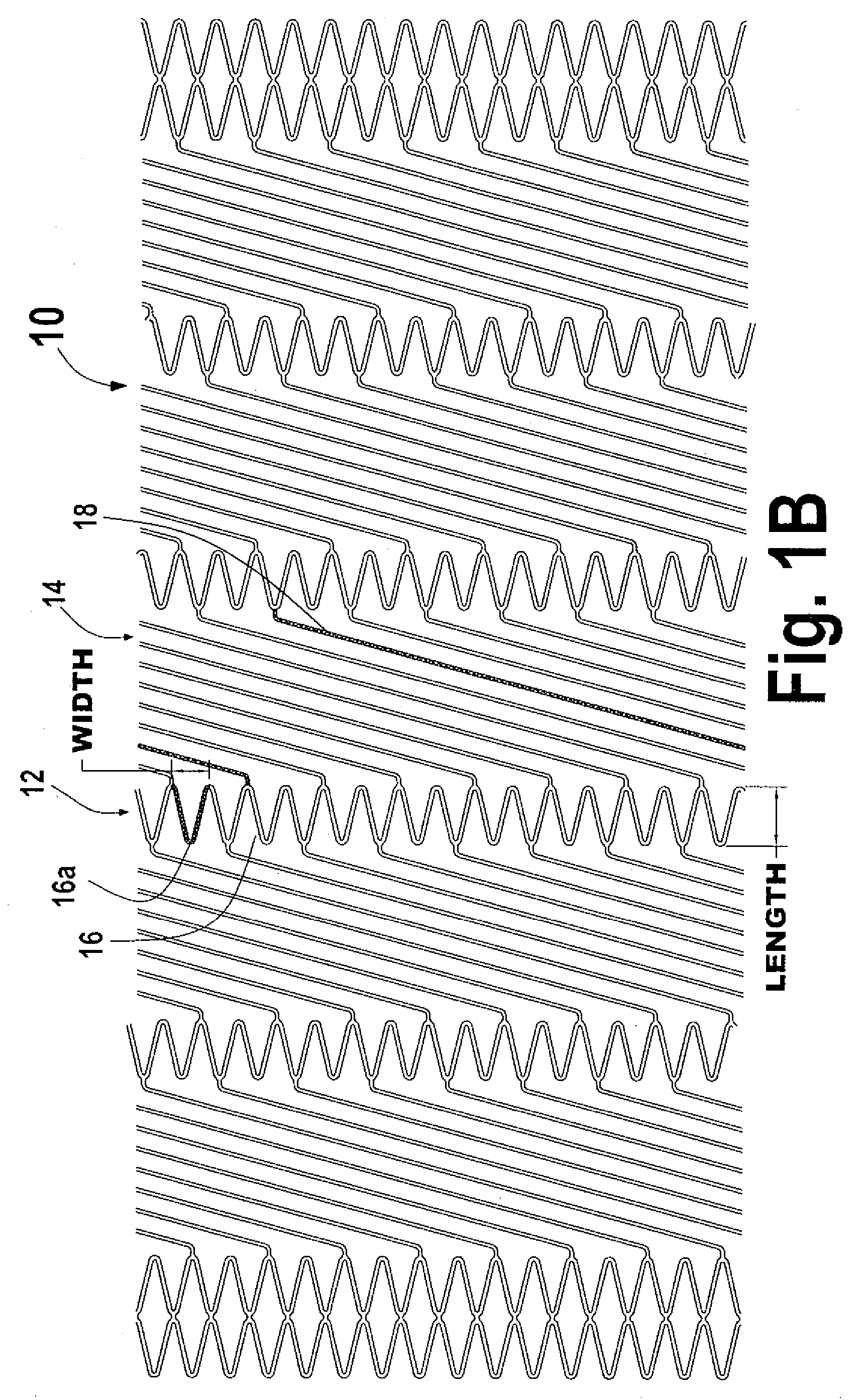
[0046]FIGS. 1A and 1B are plan views of stent 10 in accordance with the present invention shown in an unexpanded state and expanded state, respectively. As used herein, the term “plan view” will be understood to describe an unwrapped plan view. This could be thought of as slicing open a tubular stent along a line parallel to its axis and laying it out flat. It should therefore be appreciated that, in the actual stent, the top edge of the FIG. 1A will be joined to the lower edge.

[0047] Stent 10 is made from a common material for self expanding stents, such as Nitinol nickel-titanium alloy (Ni / Ti), as is well known in the art. Typically, the stent is laser cut from tubing, for example, with a diameter of about 5 mm (FIG. 1A). It is then expanded and set to a diameter of about 8 mm (FIG. 1B), and for pre-deployment it would be crimped to a diameter appropriate for the application, for example about 3 mm. However, it is contemplated that the present invention is applicable to any type a...

second embodiment

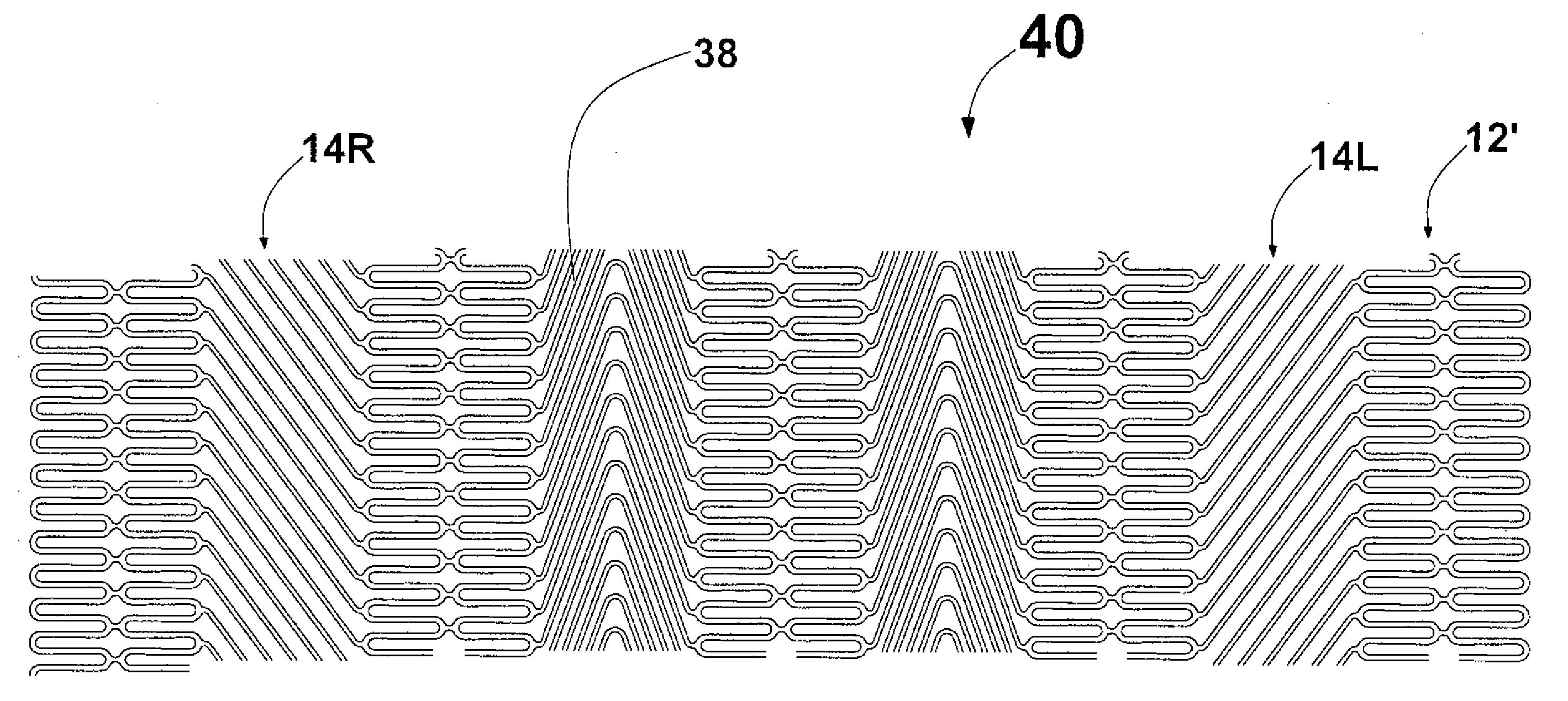
[0051]FIG. 2 is a plan view of stent 20 similar to stent 10 of FIG. 1. The primary differences are in the structure of strut portions 12′ and that there are right-handed and left-handed helical portions (14R and 14L, respectively). Each strut portion 12′ comprises two adjacent strut rings 26, 27 connected by short link 28. The closely opposed peaks of strut elements 26a, 27a are connected by short link 28, so that each strut portion 12′ has a double strut ring structure. It would also be possible to connect multiple strut rings together to form a larger strut portion. The advantage of twin or multiple strut ring strut portions is that they offer increased radial stiffness over the single strut ring strut portion and can stabilize the strut portions so they are less affected by axial forces.

[0052] In a right-handed helical portion 14R, the elements 18 progress clockwise about the surface of stent 10 and, in a left-handed helical portion 14L, they progress counterclockwise. Helical el...

fourth embodiment

[0054]FIG. 4 is a plan view of a stent in accordance with the present invention. In this case, stent 40 has strut portions 12′ of FIG. 2 and the helical portions 14L, 14R (FIG. 2) and helical portions 34 (FIG. 3). The advantage of this construction is that combining different types of helical elements allows a mix of properties as described herein, providing the opportunity for further optimization of overall stent performance for a given application.


PUM


Abstract

A flexible stent structure includes a plurality of axially spaced strut portions defining generally tubular axial segments of the stent and constructed to be radially expandable. A helical portion is interposed axially between two strut portions and has a plurality of helical elements connected between circumferentially spaced locations on the two strut portions. The helical elements extend helically between those locations and the length of a helical element is sufficient so that, when the stent is in a radially expanded state, it can simultaneously withstand repeated axial compression or expansion and bending.

Description

CROSS REFERENCE TO RELATED APPLICATION [0001] This application is a continuation of U.S. patent application Ser. No. 11 / 397,987 filed Apr. 4, 2006, which is a continuation-in-part of U.S. patent application Ser. No. 11 / 250,226 filed Oct. 14, 2005 which claims the benefit of U.S. Provisional Patent Application No. 60 / 667,613 filed Apr. 4, 2005 the entirety of each of which is hereby incorporated by reference into this application.BACKGROUND OF THE INVENTION [0002] The present invention relates generally to expandable tubular structures capable of insertion into small spaces in living bodies and, more particularly, concerns a stent structure which is capable of substantial and repeated flexing at points along its length without mechanical failures and with no substantial changes in its geometry. [0003] A stent is a tubular structure that, in a radially compressed or crimped state, may be inserted into a confined space in a living body, such as an artery or other vessel. After insertio...

Claims


Application Information

Patent Timeline
Patent Type & Authority Applications(United States)
IPC IPC(8): A61F2/88A61F2/90
CPCA61F2/07A61F2230/0054A61F2/915A61F2002/91533A61F2/88A61F2/966A61F2002/91558A61F2002/91525A61F2/91
Inventor BURPEE, JANETBEACH, BRANDLEY
Owner FLEXIBLE STENTING SOLUTIONS
Why Eureka
Try Eureka