
Portable Electric Curling Iron

Inactive Publication Date: 2007-09-13
CHOI YOUNG MAN +1
View PDF4 Cites 27 Cited by
  • Summary
  • Abstract
  • Description
  • Claims
  • Application Information

AI Technical Summary

Benefits of technology

[0007] Therefore, the present invention has been made in view of the above problems, and it is an object of the present invention to provide a portable electric curling iron having heating members that are retracted into and extended from an iron body of the electric curling ion, whereby the size of the portable electric curling iron is reduced, and therefore, the portable electric curling iron is stowed or carried with ease and convenience.
[0008] It is another object of the present invention to provide a portable electric curling iron having switch parts that are capable of automatically turning the heating members off or on simultaneously with the retraction or extension of the heating members into or from the iron body, whereby the convenience of the portable electric curling iron is maximized.
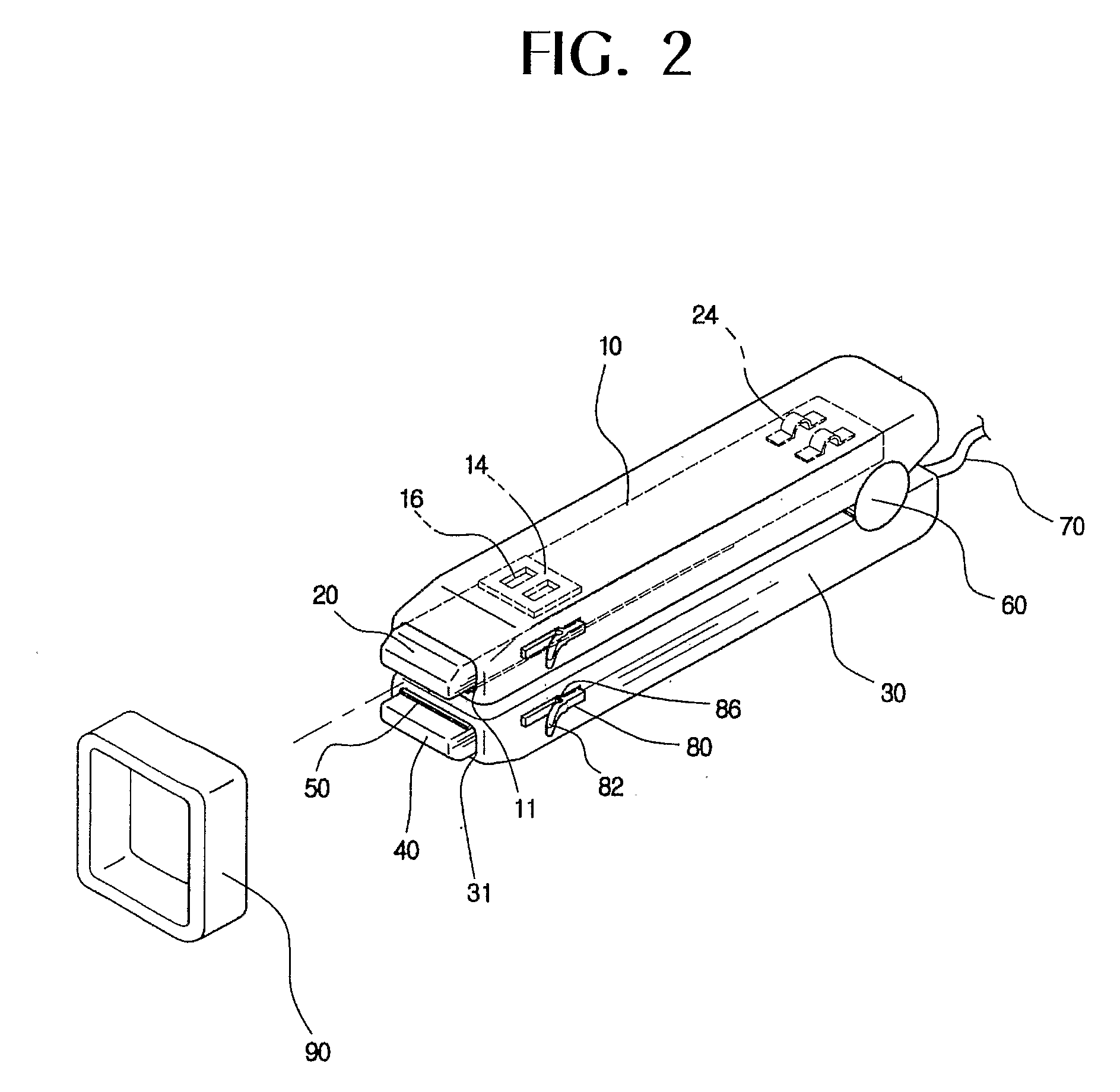
[0013] According to the present invention with the above-stated construction, the upper and lower movable iron bodies, to which the heating members are attached, are retracted into the upper and lower stationary iron bodies, respectively, whereby the portability of the portable electric curling iron is improved. Furthermore, a user can easily extend the upper and lower movable iron bodies, to which the heating members are attached, from the upper and lower stationary iron bodies, respectively, when the user wishes to use the electric curling iron, whereby the convenience of the portable electric curling iron is improved.

Problems solved by technology

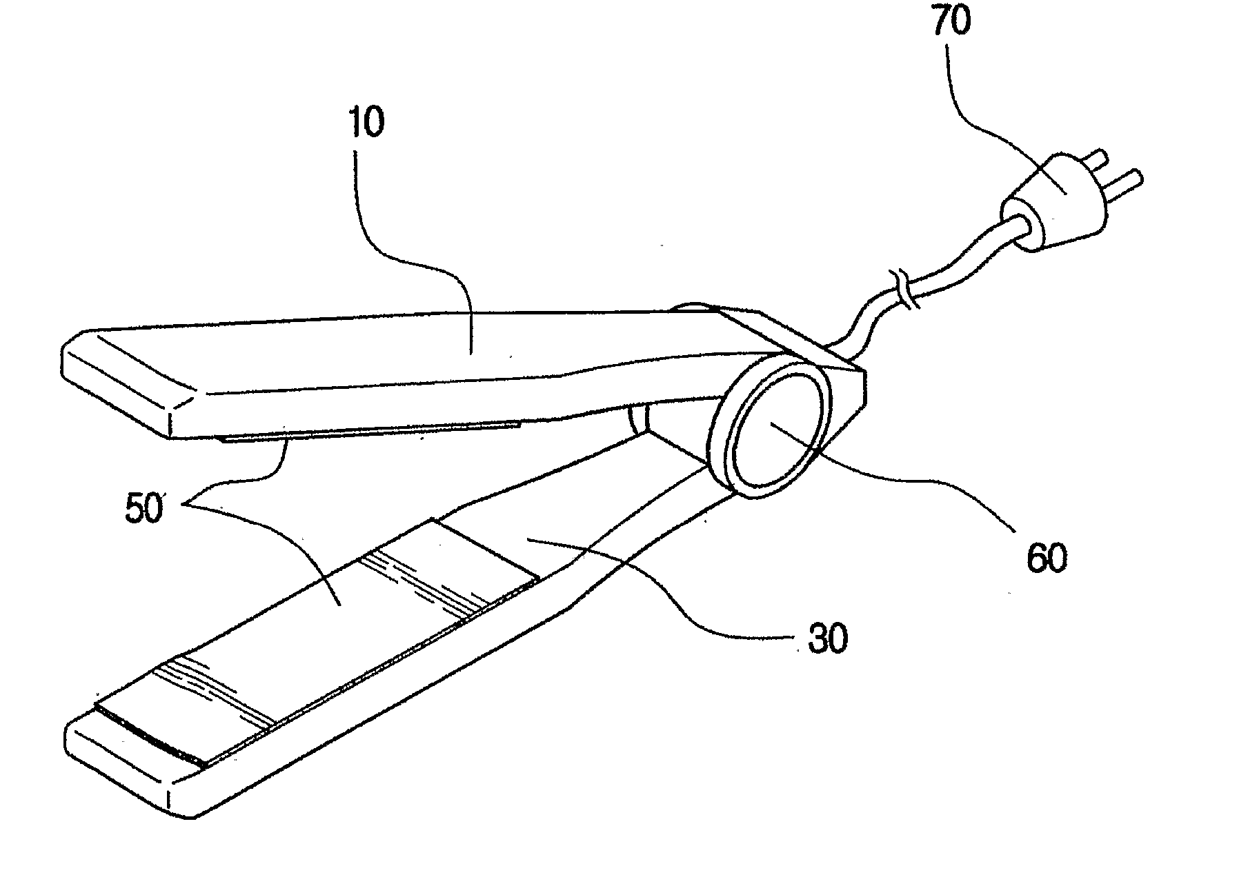
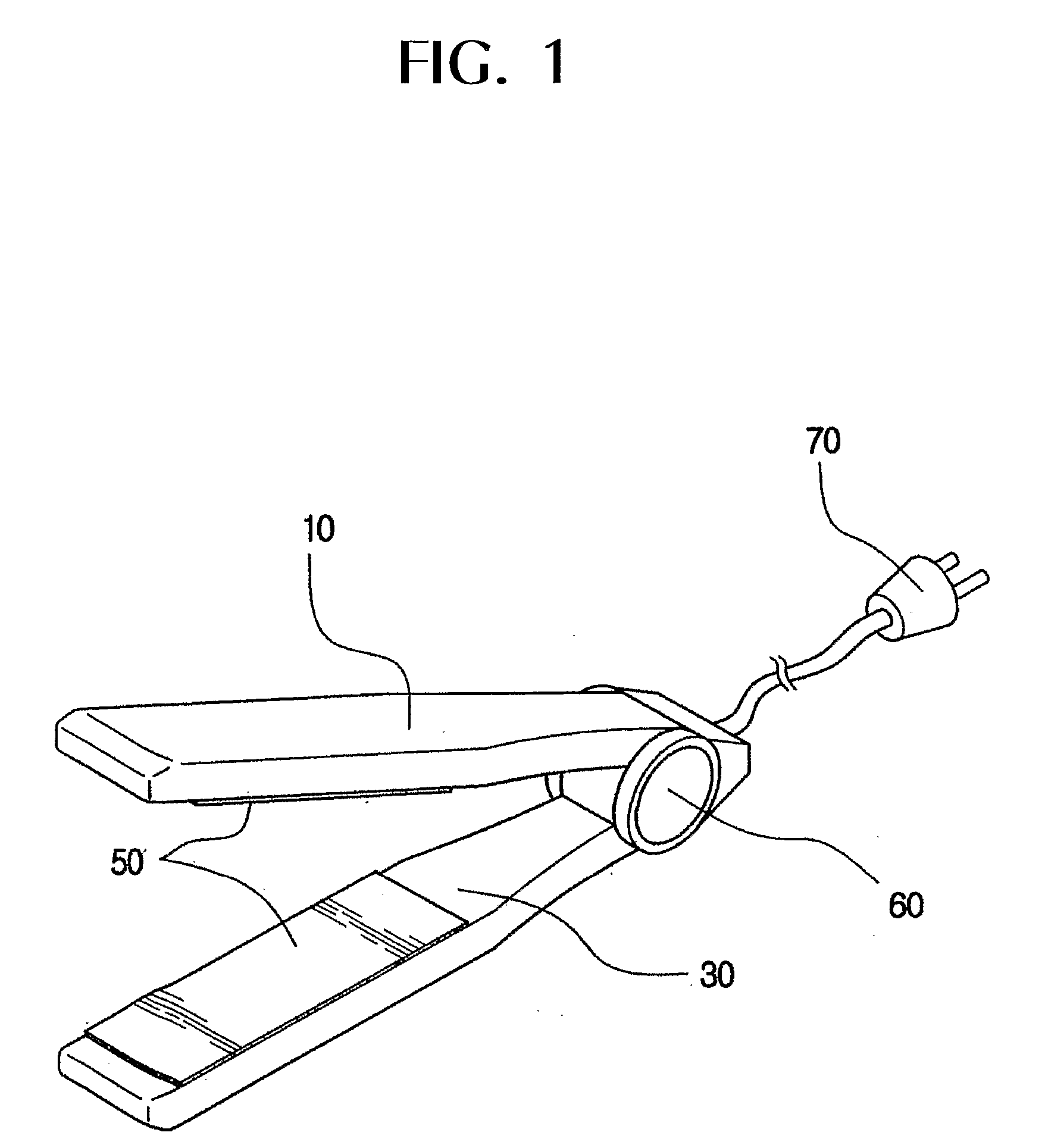
In the conventional electric curling iron with the above-stated construction, however, the upper and lower iron bodies of the electric curling iron each have a fixed length, which increases the overall size of the electric curling iron, and therefore, portability of the electric curling iron is very low.

Method used


Image

  • Portable Electric Curling Iron
  • Portable Electric Curling Iron
  • Portable Electric Curling Iron

Examples


Embodiment Construction

[0020] Now, a preferred embodiment of the present invention will be described in detail with reference to the accompanying drawings.

[0021]FIG. 2 is a perspective view illustrating a portable electric curling iron according to the present invention, FIG. 3 is a perspective view illustrating how the portable electric curling iron according to the present invention is used, FIGS. 4A and 4B are side views, in section, illustrating heating members of the portable electric curling iron according to the present invention in retracted and extended states, respectively, and FIGS. 5A and 5B are plan views, in section, illustrating the heating members of the portable electric curling iron according to the present invention in the retracted and extended states, respectively.

[0022] As shown in FIGS. 2 to 5B, the portable electric curling iron comprises: an upper stationary iron body 10 formed in the shape of a bar having a predetermined length; and a lower stationary iron body 30 formed in the...


PUM


Abstract

A portable electric curling iron comprises an upper movable iron body (20) and a lower movable iron body (40), which are connected to an upper stationary iron body (10) and a lower stationary iron body (30), respectively, such that the upper and lower movable iron bodies (20, 40) can be selectively retracted into an extended from the upper and lower stationary iron bodies (10, 30) through openings (11, 31) respectively. The upper and lower movable iron bodies (20, 40) are provided with guide grooves (22, 42), in which guide protrutions (12, 32) formed at the upper and lower stationary iron bodies (10, 30) are engaged, respectively, such that the guide protrutions (12, 32) can be guided along the corresponding guide grooves (22, 42). Heating members (50) are attached to the upper and lower movable iron bodies (20, 40), respectively, while being opposite to each other.

Description

TECHNICAL FIELD [0001] The present invention relates to a portable electric curling iron, and, more particularly, to a portable electric curling iron having heating members that are retracted into and extended from an iron body of the electric curling iron, whereby portability of the electric curling iron is improved. BACKGROUND ART [0002] Generally, individual unique hairstyles play an important part in appearance or first impressions. [0003] This is particularly important to women, who curl their hair in various different hairstyles according to their dresses and accessories or surroundings and circumstances to represent their unique personalities and senses of beauty. For this reason, women frequently change their hairstyles. [0004] Correspondingly, electric curling irons, constructed for women to curl their hair in various different hairstyles without time and spatial limits, have been increasingly used. [0005]FIG. 1 is a perspective view illustrating a conventional electric cur...

Claims


Application Information

Patent Timeline
IPC IPC(8): A45D2/40A45D1/04A45D1/06
CPCA45D1/06A45D1/04
Inventor CHOI, YOUNG MAN
Owner CHOI YOUNG MAN
Learn More