Satellite dish antenna mounting system
- Summary
- Abstract
- Description
- Claims
- Application Information
AI Technical Summary
Benefits of technology
Problems solved by technology
Method used
Image
Examples
Embodiment Construction
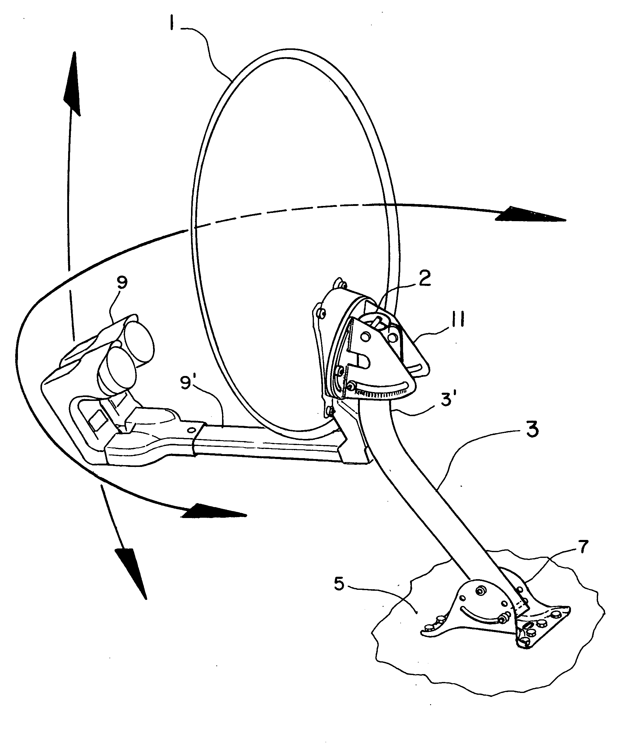
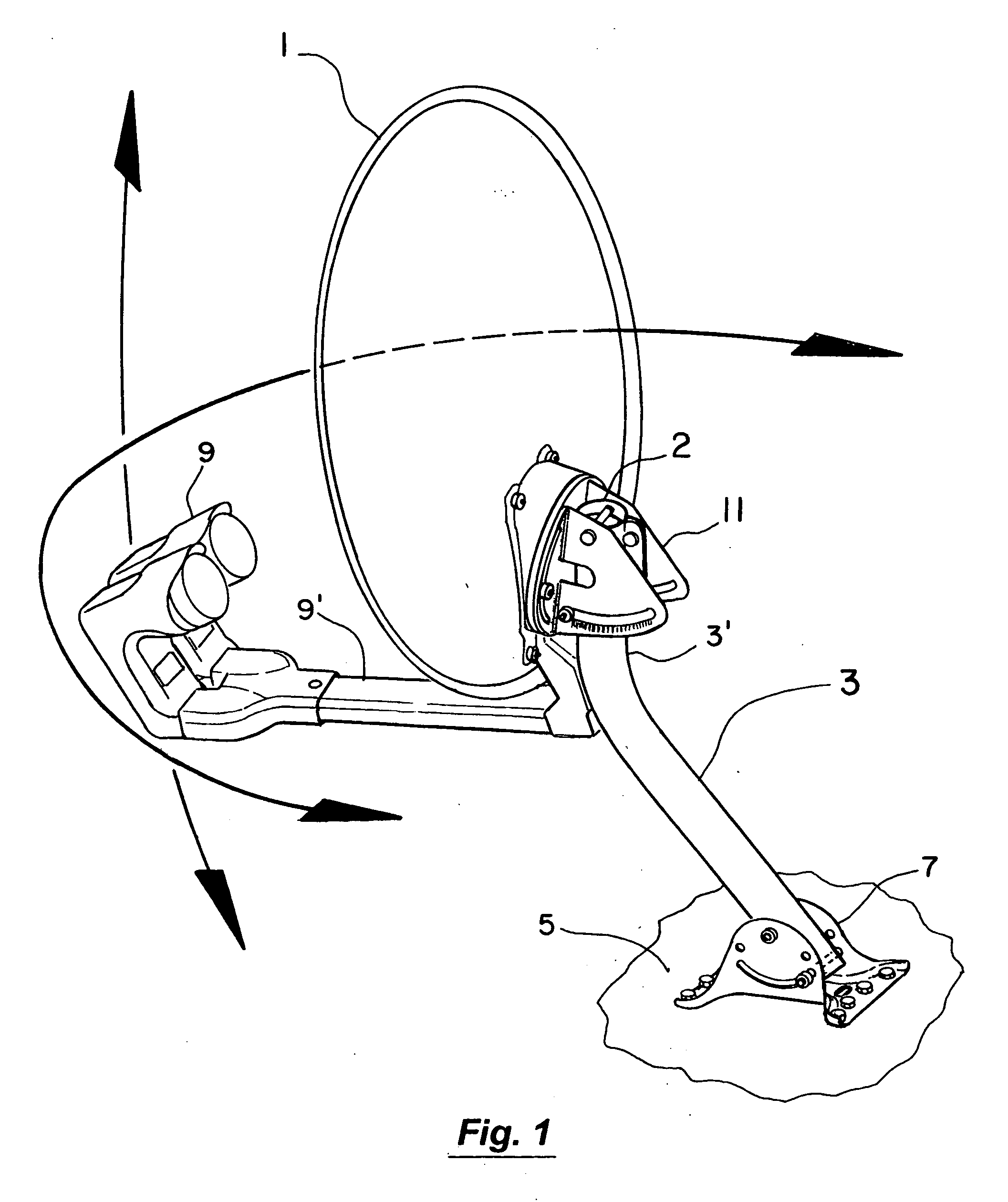
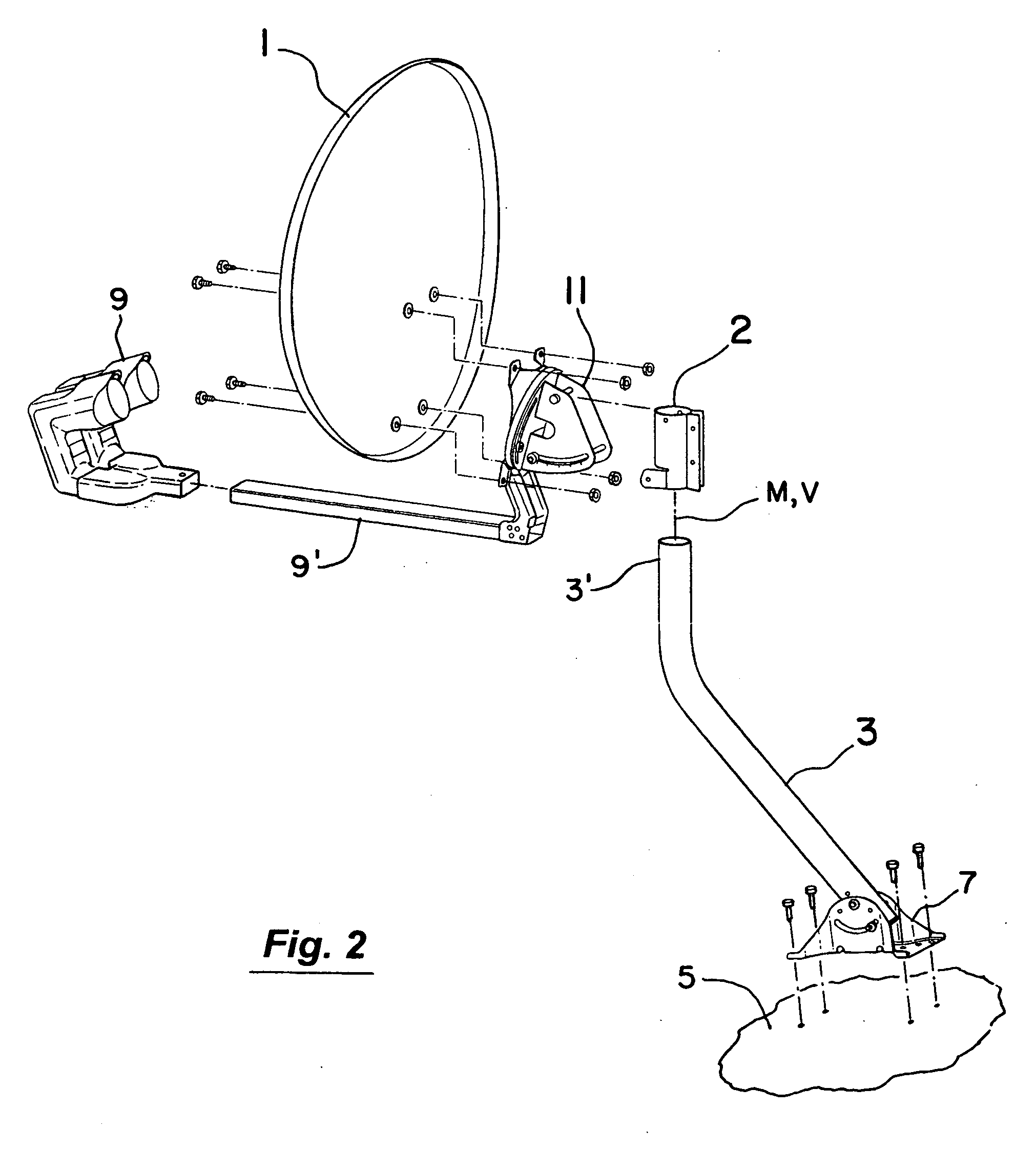
[0027] In FIG. 1, the antenna dish 1 is shown mounted on the mast 3. The mast 3 in turn is secured to a fixed object such as the roof 5 of a house by the mounting foot 7. The illustrated arrangement of FIGS. 1 and 2 also includes the feed horn 9, its support arm 9′, elevation bracket 11, and mast clamp 2. In assembling the basic elements of FIGS. 1 and 2, the antenna dish 1 (see FIG. 2) is attached to the elevation bracket 11 along with the support arm 9′ and feed horn 9. With the elevation bracket 11 then secured to the mast clamp 2 (FIGS. 3-4), the assemblage 15 (FIG. 4) of the antenna dish 1, feed horn 9, support arm 9′, elevation bracket 11, and mast clamp 2 can be manually manipulated as a unit and secured in place on the upper section 3′ of the mast 3 (FIGS. 5-6).
[0028] In doing so, the mast clamp 2 as best seen in FIGS. 7-9 has a tab or clip member 4 extending downwardly and inwardly from the main body 2′ of the mast clamp 2. As the mast clamp 2 of FIG. 7 (with the attached ...
PUM
 Abstract
Description
Claims
Application Information
 - R&D
- Intellectual Property
- Life Sciences
- Materials
- Tech Scout
- Unparalleled Data Quality
- Higher Quality Content
- 60% Fewer Hallucinations
Browse by: Latest US Patents, China's latest patents, Technical Efficacy Thesaurus, Application Domain, Technology Topic, Popular Technical Reports.
© 2025 PatSnap. All rights reserved.Legal|Privacy policy|Modern Slavery Act Transparency Statement|Sitemap|About US| Contact US: help@patsnap.com


