Satellite dish antenna mounting system

a satellite dish and mounting system technology, applied in the direction of antennas, antenna details, electrical equipment, etc., can solve the problems of affecting the elevation alignment of the dish, the difficulty of simultaneous manual support of the assemblage, and the difficulty of one installer to simultaneously support the assemblage, so as to achieve quick and efficient alignment of the satellite antenna system

Inactive Publication Date: 2008-06-10
WINEGARD
View PDF13 Cites 24 Cited by
  • Summary
  • Abstract
  • Description
  • Claims
  • Application Information

AI Technical Summary

Benefits of technology

[0009]This invention involves a satellite antenna mounting system primarily for residential homes. In it, a downwardly inclined tab or clip member is provided on the main body of the clamp to which the assemblage of the dish, feed horn, and elevation bracket are attached. In operation, the clamp of the assemblage can be lowered to receive the upper portion of the mast which is affixed to the roof or other part of the house. In doing so, the clip member engages the upper rim of the mast and firmly attaches or clips the assemblage to the mast with the dish in its desired elevation. Thereafter, the loose clamp can be tightened about the upper portion of the mast at the desired azimuth without affecting the set elevation of the dish.
[0010]In this manner, the independent operation of the elevation and azimuth settings allows for quick and efficient alignment of the satellite antenna system on the house. In effect and unlike current systems, the dish elevation can be correctly set prior to locking or clamping the dish on the mast in the desired azimuth position.

Problems solved by technology

A problem in this basic installation procedure is that the weight of the assemblage of the dish, attached feed horn, elevation bracket, and clamp is virtually all on one side of the axis of the clamp.
Consequently, it is extremely difficult for one installer to simultaneously manually support the assemblage, guide its clamp onto the mast, rotate the assemblage about the vertical axis of the mast, and tighten the clamp on the mast.
This is particularly difficult if it is windy and / or the antenna is being mounted in tight or awkward quarters.
To the extent any re-adjustment of the elevation adversely affects the desired azimuth setting, the entire procedure may have to repeated once or even several times. The fundamental problem with such current antenna mounts of this kind is that the tightening step of the clamp to lock in the azimuth is not independent of and in fact affects the elevation alignment of the dish.

Method used


Image

  • Satellite dish antenna mounting system
  • Satellite dish antenna mounting system
  • Satellite dish antenna mounting system

Examples


Embodiment Construction

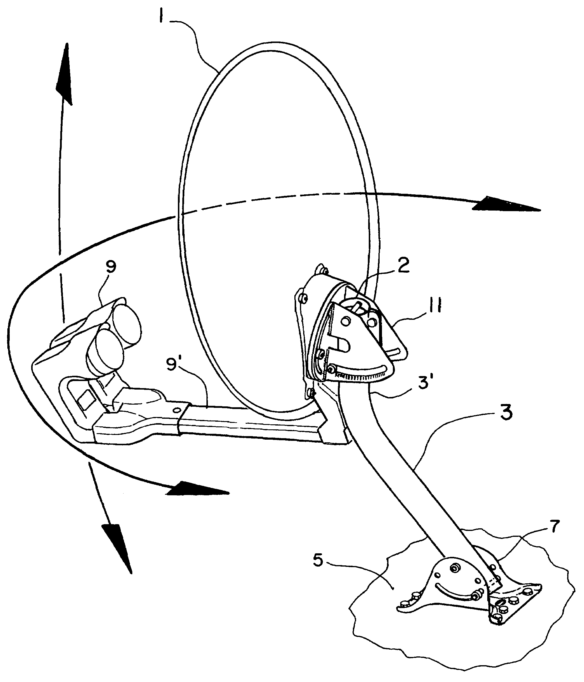
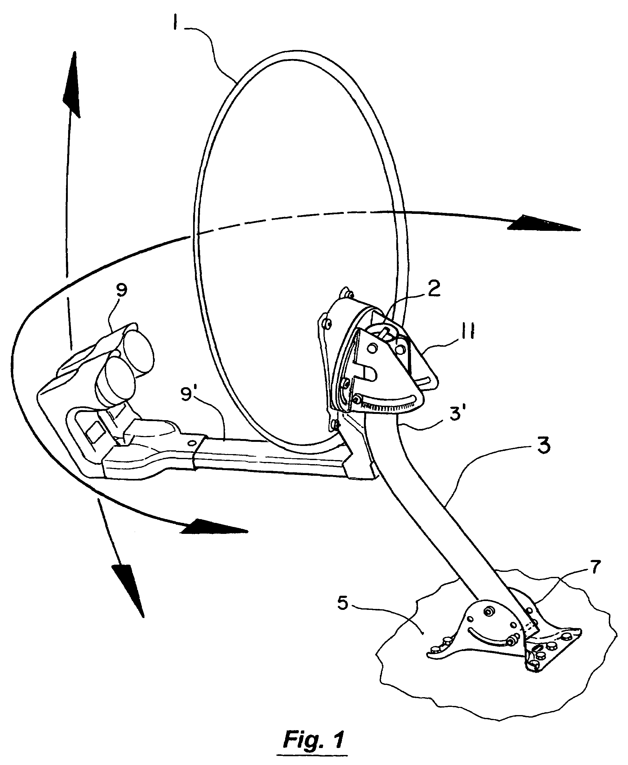
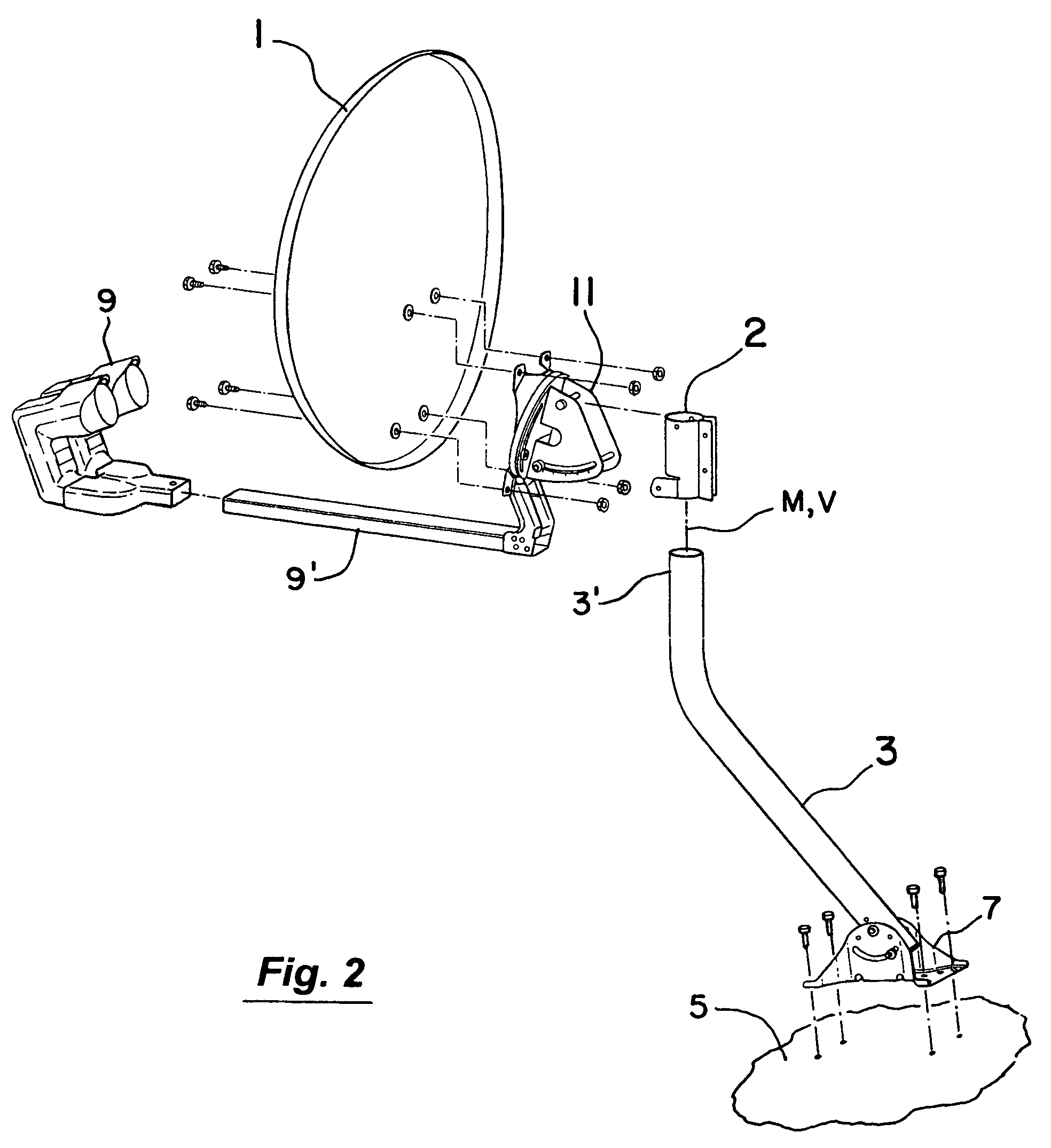
[0027]In FIG. 1, the antenna dish 1 is shown mounted on the mast 3. The mast 3 in turn is secured to a fixed object such as the roof 5 of a house by the mounting foot 7. The illustrated arrangement of FIGS. 1 and 2 also includes the feed horn 9, its support arm 9′, elevation bracket 11, and mast clamp 2. In assembling the basic elements of FIGS. 1 and 2, the antenna dish 1 (see FIG. 2) is attached to the elevation bracket 11 along with the support arm 9′ and feed horn 9. With the elevation bracket 11 then secured to the mast clamp 2 (FIGS. 3-4), the assemblage 15 (FIG. 4) of the antenna dish 1, feed horn 9, support arm 9′, elevation bracket 11, and mast clamp 2 can be manually manipulated as a unit and secured in place on the upper section 3′ of the mast 3 (FIGS. 5-6).

[0028]In doing so, the mast clamp 2 as best seen in FIGS. 7-9 has a tab or clip member 4 extending downwardly and inwardly from the main body 2′ of the mast clamp 2. As the mast clamp 2 of FIG. 7 (with the attached ele...


PUM


Abstract

A satellite antenna mounting system primarily for residential homes including a dish, feed horn, elevation, clamp, and mast. The main body of the clamp to which the assemblage of the dish, feed horn, and elevation bracket are attached is provided with a downwardly inclined tab or clip member. In operation, the clamp of the assemblage can be lowered to receive the upper portion of the mast which is affixed to the roof or other part of the house. In doing so, the clip member engages the upper rim of the mast and firmly attaches or clips the assemblage to the mast with the dish in its desired elevation. Thereafter, the loose clamp can be tightened about the upper portion of the mast at the desired azimuth without affecting the set elevation of the dish.

Description

RELATED APPLICATIONS[0001]This application claims the benefit of U.S. Provisional Patent Application Ser. No. 60 / 781,427 filed Mar. 10, 2006, which is incorporated herein by reference.BACKGROUND OF THE INVENTION[0002]1. Field of the Invention[0003]This invention relates to the field of antenna mounts and more particularly to the field of satellite dish antenna mounts primarily for residential use.[0004]2. Discussion of the Background[0005]Residential dish antennas for satellite reception are commonly mounted by one person on a customer's house (e.g., roof or wall). In installing the antenna, the dish is first typically secured to an elevation bracket which in turn is adjustably attached to a mast clamp. Such mast clamps commonly have a C-shape and can be secured about a vertically extending portion of a mast that is fixed to the roof or other part of the house. In doing so, the upper portion of the mast is initially received in the loose clamp. The clamp is then further lowered onto...

Claims


Application Information

Patent Timeline
Patent Type & Authority Patents(United States)
IPC IPC(8): H01Q1/12
CPCH01Q1/125H01Q3/08
Inventor ZIHLMAN, BRIAN STEVEN
Owner WINEGARD
Why Eureka
Try Eureka