
Apparatus and method for liquid level measurement and content purity measurement in a sounding tube

a technology of liquid level measurement and content purity, applied in liquid/fluent solid measurement, instruments, machines/engines, etc., can solve problems such as visual examination obstruction, degrade performance, damage to jet components, etc., and achieve optimal polarization of the gauge, quick, efficient alignment

Active Publication Date: 2021-08-10
VEGA AMERICAS
View PDF14 Cites 0 Cited by
  • Summary
  • Abstract
  • Description
  • Claims
  • Application Information

AI Technical Summary

Benefits of technology

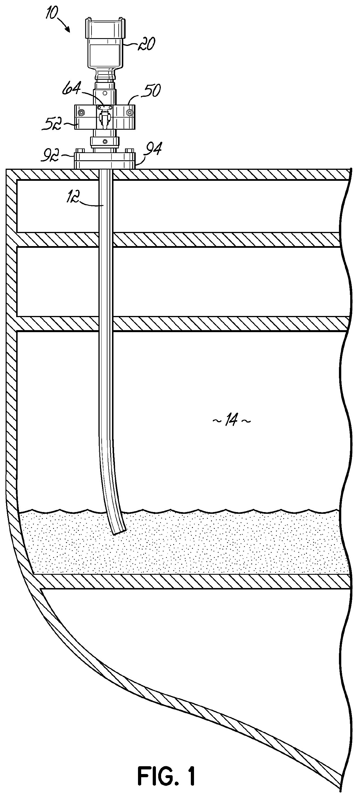
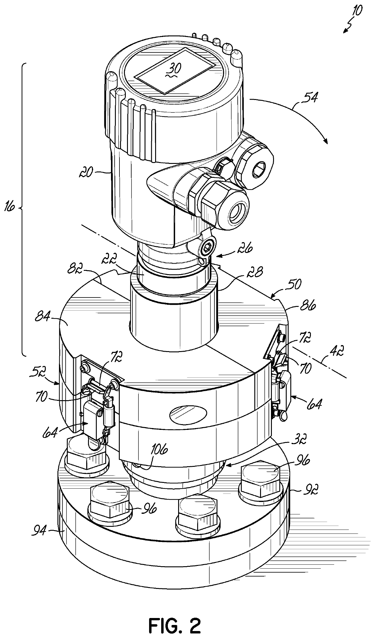
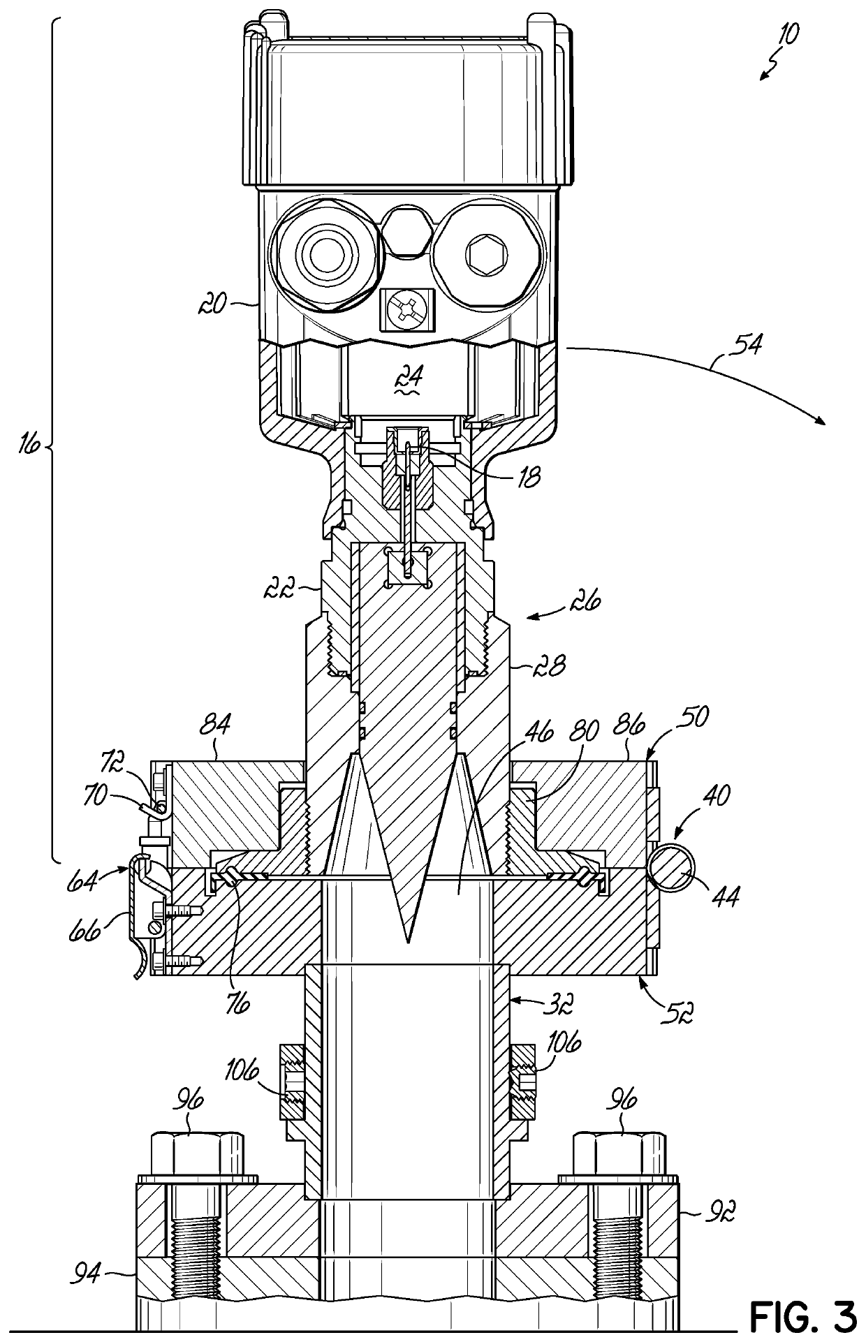
[0012]The level sensing apparatus and liquid level and content purity measurement methods described herein improve upon the aforementioned apparatus and methods by providing apparatus for rotating the level sensing gauge away from the sounding tube. As will be described herein, the improved level sensing apparatus can be rotated away from the sounding tube to fully expose the open end of the tube, and thereby allow access to the sounding tube for insertion of a thief sampler, plumb line and bob, or other manually insertable measuring device. Additionally, in the improved level sensing apparatus the connecting assembly between the level sensing gauge and sounding tube adaptor is separable to allow for removal and replacement of the level sensing gauge without the need to remove the sounding tube adaptor from the sounding tube. Further, the improved level sensing apparatus and methods provide for quick, efficient alignment between the antenna and sounding tube to optimally polarize the gauge following rotation of the gauge housing.

Problems solved by technology

Contaminates in the fuel can cause damage to jet components and can degrade performance in a manner that is hazardous to the occupants.
In the particular situation of jet fuel on Naval ships, visual examination is obstructed by the location of the tanks within the bowels of the ship and by the voluminous size of the tanks.
Certain problems arise, however, from the plumb line method of liquid level measurement.
First, jet fuel is clear and evaporates very rapidly, thereby enhancing the difficulty of visually assessing the plumb line to accurately determine the associated moisture level.
Second, the plumb bob may break off the plumb line during use.
Due to the difficulty involved, as a practical matter detached plumb bobs are not retrieved from sounding tubes.
As a result, subsequent plumb bobs used for measurement may be impeded from falling to the bottom of the sounding tube, resulting in reduced measurement range.
While non-contact radar level sensing gauges have many advantages, problems can arise with these gauges when attempting the back-up manual sounding method of level measurement and fuel purity checks, as practiced by the Navy.
Removal of the level sensing gauge from the sounding tube in order to use the plumb line is unwieldy and time consuming, and requires placing the highly sensitive gauge on the deck of the ship.
In this location, the gauge is vulnerable to damage.
Additionally, after a sample has been taken, the level sensing gauge must be reattached to the sounding tube, which can be time-consuming and require a recalibration of the gauge.
While these apparatus and methods have proven adequate for measuring the level of contents in storage tanks using both non-contact radar and manual, plumb line methods, the location of the latch door in the apparatus does not allow for samples of the tank contents to be collected in order to measure the purity of the fuel.
In particular, the position of the latch door in the sidewall of the sounding tube adaptor is not suitable for insertion of a thief sampler.
While this level sensing gauge eliminates the need to remove the gauge from the sounding tube to perform manual measurements, and also allows for the use of a thief sampler to collect fuel samples, the need to lift the apparatus prior to swiveling is awkward and requires a minimum of overhead room.
Additionally, the lifting and swiveling movements can be unwieldy in the tight space available on a Naval ship.
Additionally, during the lifting and swiveling motions the antenna in the gauge can lose alignment with the sounding tube, necessitating a recalibration.

Method used


Image

  • Apparatus and method for liquid level measurement and content purity measurement in a sounding tube
  • Apparatus and method for liquid level measurement and content purity measurement in a sounding tube
  • Apparatus and method for liquid level measurement and content purity measurement in a sounding tube

Examples


first embodiment

[0049]A clamp 130, having a pair of releasably-connected, semi-circular segments, encircles the apparatus 110 for connecting the housing 16 to the first flange 122 of the connector assembly 120. Referring to FIGS. 10 and 11, clamp 130 has a recessed interior area 132 extending about the circumference of the clamp. As described in the first embodiment, a lap joint 80 encircles the base of the antenna shield 28. Clamp 130 engages a flange 134 on the lap joint 80 within the interior area 132. Lap joint 80 has a planar bottom surface 136 which abuts a planar top surface 140 of the upper flange 122. One or more sealing members, such as, for example, an o-ring 142, are positioned between the planar surfaces 136, 140 to seal the opening between the surfaces. Clamp 130 engages the outer circumference of the lap joint 80 and upper flange 122 to lock the edges together. Clamp 130 is formed in two semi-circular halves connected by releasable fasteners 144. When connected, clamp 130 locks appar...

third embodiment

[0052]FIGS. 14A and 14B illustrate a third embodiment for handle 160. In this embodiment, the handle includes a pull member 212, and a link member 214 having a through hole 216 at one end for engaging pin 154. At least one locking washer 220 is attached to the opposite end of the link member 214, such as by screw threads, in a recessed area 222 at the base of pull member 212. The position of washer 220 on link member 214 may be adjusted relative to the pin 154 to alter the distance between the pull member 212 and the pin. Washer 220 can have apertures designed for receiving a specialized fitting 224. Fitting 224 can be attached to a torque wrench to provide the correct adjustment of the washer. Using a specialized fitting 224 allows for increased control over the washer adjustment. The fitting 224 depicted in FIG. 14B is merely representative of the type of fitting that may be used to adjust washer 220. Other types of fittings, having a variety of configurations, may be used in orde...


PUM

PropertyMeasurementUnit
angleaaaaaaaaaa
axis of symmetryaaaaaaaaaa
mechanicalaaaaaaaaaa

Abstract

A level sensing apparatus (110) for attachment to a sounding tube to measure levels of content in a tank. The level sensing apparatus includes a housing (16) for enclosing components of the level sensing apparatus (20). These components include a transmitter and an antenna (18) operatively connected to the transmitter for directing electrical or mechanical waves in a direction away from the transmitter. The antenna is adapted to also receive electrical and mechanical waves. The apparatus further includes a sounding tube adaptor (32) sized for attachment to a sounding tube, and a connector assembly operatively attaching the housing to the sounding tube adaptor. The connector assembly enabling the housing to rotate relative to the sounding tube adaptor about a horizontal axis to expose an open end of the sounding tube. In use, the level sensing apparatus allows for pulse radar measurement of liquid levels in the tank. The housing may be rotated relative to the sounding tube to also allow for manual level measurements or sampling of the tank contents.

Description

FIELD OF THE INVENTION[0001]The present invention relates to pulse radar measurement and, more particularly, to a level sensing apparatus and method using pulse radar waves to measure the level of liquid in a storage tank while also allowing for manual measurement of the liquid.BACKGROUND OF THE INVENTION[0002]In many environments, various materials are stored and / or processed in tanks prior to or during their disposition. These materials include foods, beverages, pharmaceuticals and fuels. One particular and commonly-known use of such tanks involves the storage of fuel for various modes of transportation. These fuel tanks can range from a gas tank on a car to voluminous fuel tanks such as those located on Naval ships. In particular, aircraft carriers house multiple fuel tanks. These tanks are used to store jet fuel for the aircraft carried on the ship.[0003]With storage tanks on Naval vessels, the ability to reliably determine the amount and purity of the contents of the tanks at a...

Claims


Application Information

Patent Timeline
Patent Type & Authority Patents(United States)
IPC IPC(8): G01F23/22G01N33/00G01F23/00G01F23/284G01F23/296G01F23/04
CPCG01F23/22G01F23/0023G01F23/04G01F23/284G01F23/296G01N33/00
Inventor RIVERA, ESTHER MILAGROS DÍAZGARRETT, GREGGORY JAMESCONLEY, MICHAEL RAYWILKIE, NEIL T.
Owner VEGA AMERICAS
Learn More