Optical film having low chromaticity variation and quarter wavelength plate, and liquid crystal display using the same

a technology of optical film and quarter wavelength plate, applied in the field of optical film, can solve the problems of retardation change, film shrinkage, hue and chromaticity variation of the display screen of the liquid crystal display, etc., and achieve the effect of small chromaticity and brightness variation, excellent polarization

Inactive Publication Date: 2005-10-25
NITTO DENKO CORP
View PDF21 Cites 16 Cited by
  • Summary
  • Abstract
  • Description
  • Claims
  • Application Information

AI Technical Summary

Benefits of technology

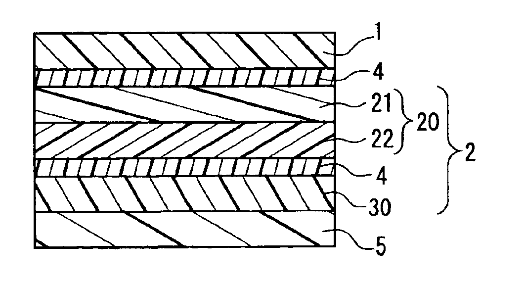
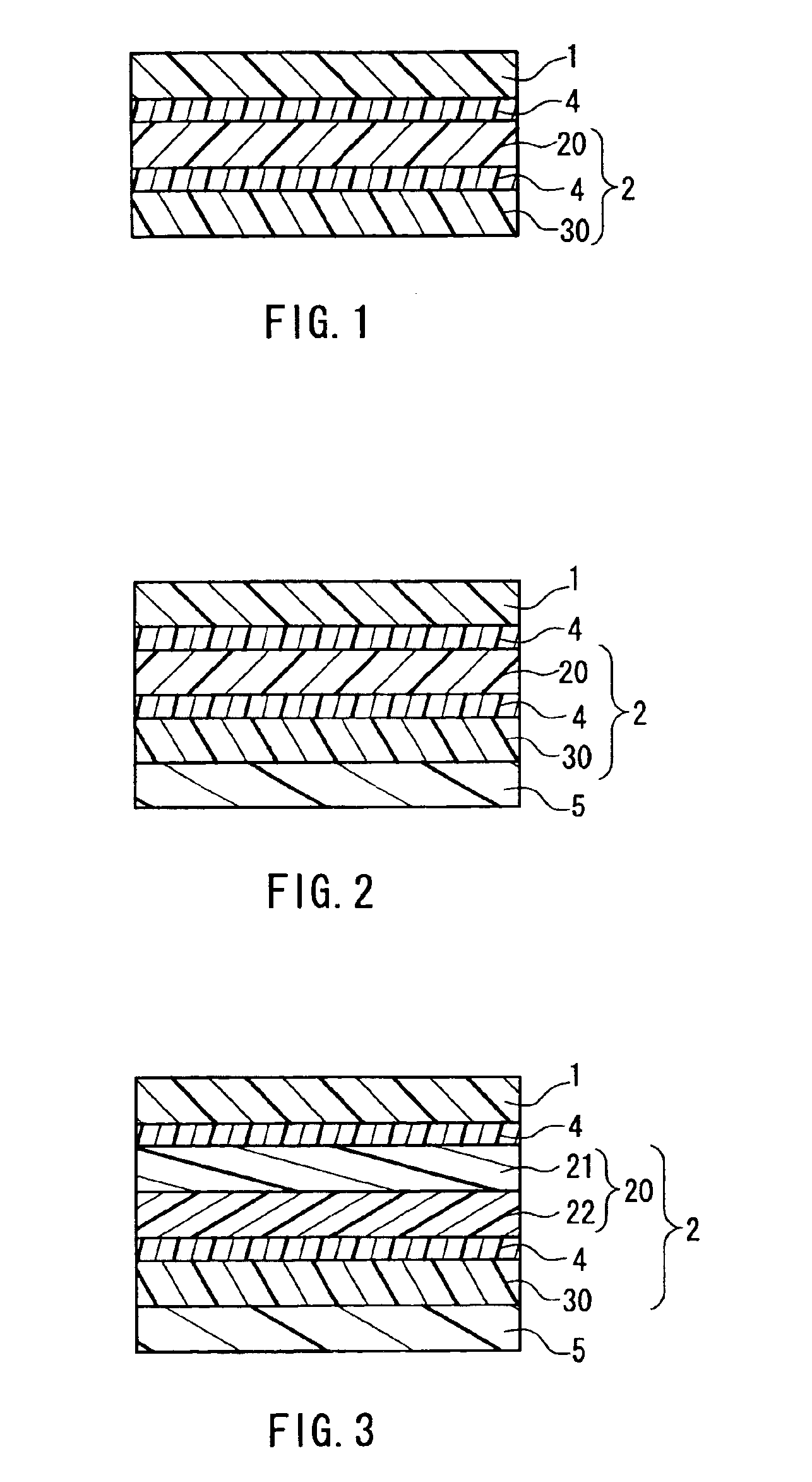
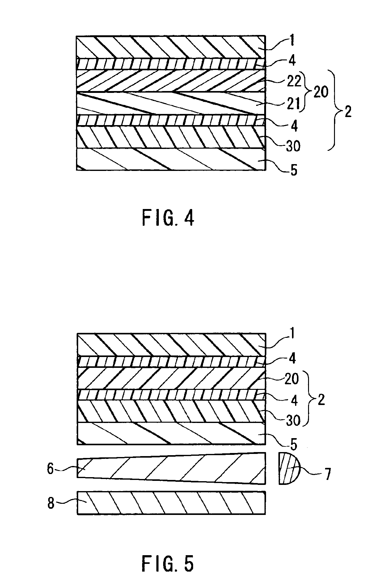
[0014]The inventors studied keenly a brightness enhancement film used in combination with a polarizing plate, in particular, a brightness enhancement film including a layer having a circularly polarized light separating (reflecting) function and a quarter wavelength plate (in the following, referred to as a “λ/4 plate”). It was then found that, by using as the λ/4 plate (1) a film having predetermined wavelength dispersion characteristics or (2) a film having a predetermined photoelastic coefficient, it was possible to suppress down t

Problems solved by technology

However, there are problems as well, which will be described below.
It is known that this stress causes shrinkage of the film under a heating or high-temperature humidifying condition.
As a result, the problem arises in that the brightness, hue and chromaticity variations occur in the display screen of the liquid crystal display.
However, even after the changes in d

Method used


Image

  • Optical film having low chromaticity variation and quarter wavelength plate, and liquid crystal display using the same
  • Optical film having low chromaticity variation and quarter wavelength plate, and liquid crystal display using the same
  • Optical film having low chromaticity variation and quarter wavelength plate, and liquid crystal display using the same

Examples


examples

[0108]The following is a more specific description of the present invention by way of examples and comparative examples, though the present invention is by no means limited to the examples below.

example a-2

[0115]A 100 μm-thick diacetylcellulose film (manufactured by Nitto Denko Corporation) showing Δnd(450 nm) / Δnd(550 nm)=0.96 was stretched uniaxially to 1.4 times its original length and used as a λ / 4 film with a thickness of 80 μm. A 300 μm-thick optical film was produced in a manner similar to Example A-1 except that this λ / 4 film was used. The obtained λ / 4 film and λ / 4 plate each had a Δnd(450 nm) / Δnd(550 nm) of 0.96, and the ?λ / 4 film had a photoelastic coefficient of 18.4×10⁻¹² m2 / N.

example a-3

[0116]For preparing a λ / 4 film, a 100 μm-thick norbornene-based polymer film (trade name ARTON; manufactured by JSR Corporation) showing Δnd(450 nm) / Δnd(550 nm)=1.01 was used as a transparent film and stretched uniaxially to 1.4 times its original length, thus preparing a λ / 4 film with a thickness of 85 μm. Then, a 305 μm-thick optical film was produced in a manner similar to Example A-1 except that this λ4 film was used as the λ / 4 plate with no nematic liquid crystal layer laminated thereon. The λ / 4 plate had a Δnd(450 nm) / Δnd(550 nm) of 1.01 and a photoelastic coefficient of 4.1×10⁻¹² m2 / N.


PUM


Abstract

An optical film in which a function of a brightness enhancement film is maintained and variations in brightness and chromaticity within a film plane are suppressed is provided. An optical film is a laminate of an absorptive dichroic polarizing plate and a brightness enhancement film. A maximum chromaticity difference Δxy(max) of in-plane transmitted light is 0.008 or smaller after the optical film is attached to a glass plate and allowed to stand at 70° C. for 120 hours. The brightness enhancement film includes a layer having a circularly polarized light separating function, and a quarter wavelength plate. The quarter wavelength plate is a film showing an in-plane retardation (Δnd) satisfying Δnd(450 nm)/Δnd(550 nm)<1.02 or a film containing a polymer having a photoelastic coefficient of 40×10−12 m2/N or smaller.

Description

[0001]The present application claims priority of Japanese applications Nos. 2002-214340 and 2002-214341, which are hereby incorporated by reference.BACKGROUND OF THE INVENTION[0002]1. Field of the Invention[0003]The present invention relates to an optical film used in various image display apparatus such as liquid crystal displays (LCDs). More specifically, the present invention relates to a laminated polarizing plate with a brightness enhancement film and various image display apparatus using the same.[0004]2. Description of Related Art[0005]Conventionally, polarizing plates often have been used in liquid crystal displays, and the demand therefor has been increasing rapidly. Furthermore, in recent years, high-value-added polarizing plates such as those having an optically compensating function have come into use. There has been expanding expectations for better display quality in terms of, for example, hue, brightness, contrast and viewing angle.[0006]For the purpose of enhancing b...

Claims


Application Information

Patent Timeline
IPC IPC(8): G02B5/30G02F1/13G02F1/1335G02F1/13363
CPCG02B5/3016G02B5/3033G02F2001/133638G02F1/133638G02F1/1335
Inventor KAWAHARA, SATORUTAKAHASHI, NAOKIMOTOMURA, HIRONORIKAWAMOTO, IKUO
Owner NITTO DENKO CORP
Why Eureka
Try Eureka