Methods of manufacturing a segmented brush seal for sealing between stationary and rotary components

a technology of rotary components and brush seals, which is applied in the field of manufacturing methods of brush seals, can solve the problems of time-consuming and costly methods of manufacturing

Inactive Publication Date: 2007-09-20
GENERAL ELECTRIC CO
View PDF49 Cites 20 Cited by
  • Summary
  • Abstract
  • Description
  • Claims
  • Application Information

AI Technical Summary

Problems solved by technology

As will be appreciated, this is a time consuming and costly method of manufacture.

Method used


Image

  • Methods of manufacturing a segmented brush seal for sealing between stationary and rotary components
  • Methods of manufacturing a segmented brush seal for sealing between stationary and rotary components
  • Methods of manufacturing a segmented brush seal for sealing between stationary and rotary components

Examples


Embodiment Construction

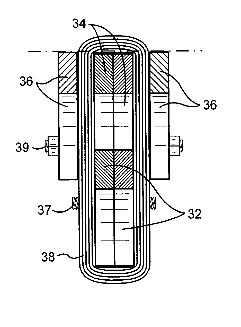
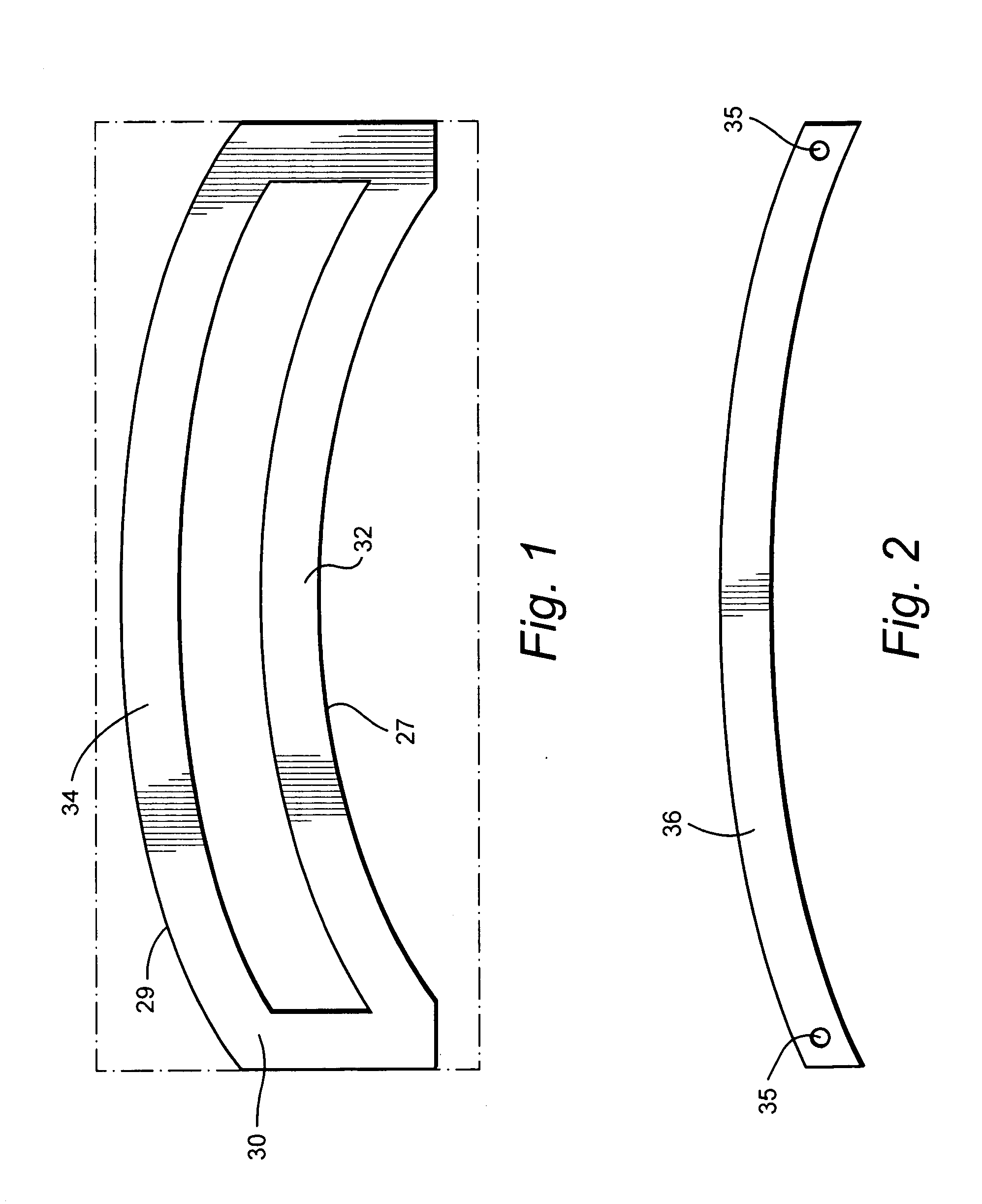
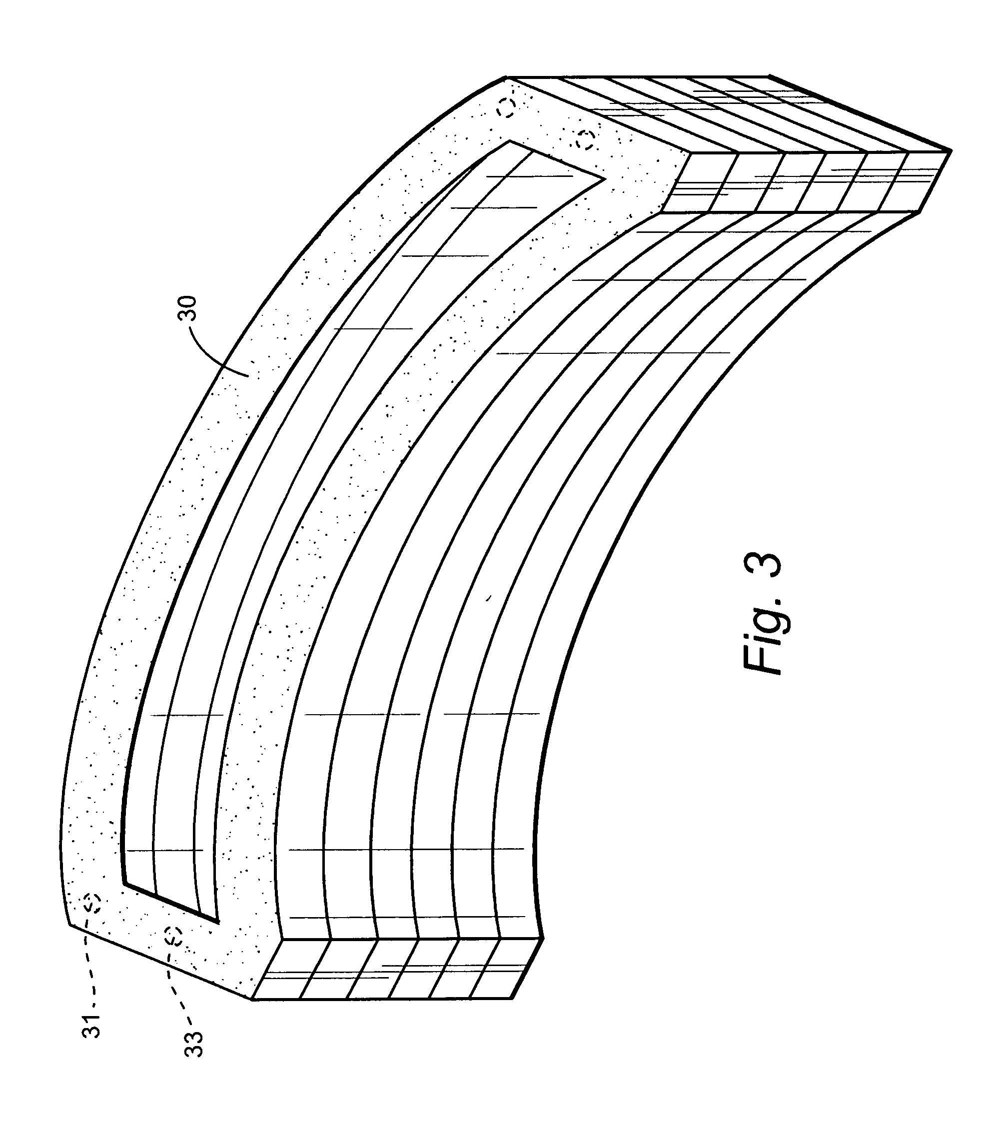
[0034] Referring now to the drawings, particularly to FIG. 13 there is illustrated a packing ring 10 including a dovetail 12 on one side for securement to a stationary component 13 and a plurality of labyrinth teeth 14 on an opposite side for sealing with a rotary component 16. As illustrated, a brush seal, generally designated 18, is disposed within an arcuate slot of the packing ring 10 and includes a plurality of bristles 20, tips of which sealingly engage along the surface of the rotary component. A pressure plate 22 and a fence 24 are machined on the packing ring and lie on respective opposite sides of the bristles 20. The brush bristles 20, as is conventional, are typically angled or canted in the direction of rotation of component 16 and each bristle forms an acute angle with an intersecting radius of rotor 16. The packing rings 10 are preferably formed in segments to complete an annular brush seal about the rotary component. Set screws, not shown, for example along the outer...


PUM

PropertyMeasurementUnit
angleaaaaaaaaaa
wrap angleaaaaaaaaaa
anglesaaaaaaaaaa

Abstract

A method of forming brush seal segments includes mounting a pair of full form plates having opposite arcuate edges in back-to-back relation and wrapping wire about the form plates in multiple passes to form wire runs at angles, e.g., 35-45° relative to radii of the arcuate edges. Half form plates are assembled to opposite sides of the full form plates adjacent one edge of the subassembly. The wire wrap adjacent the one edge of the full form plates is removed. Welds are applied between each adjacent half and full form plates. The inner edges of the wrapped wire and inner frame members of the full form plates are removed. The assembly is then separated to form a pair of arcuate brush seal segments.

Description

BACKGROUND OF THE INVENTION [0001] The present invention relates to methods of manufacturing a brush seal and particularly relates to methods of manufacturing generic brush seals to required sizes e.g., diameters in segments with enhanced efficiency, minimum costs and reduced manufacturing time. [0002] Brush seals are typically employed for sealing between stationary and rotary components, e.g., packing about a rotary shaft in a turbine, and between high and low pressure regions on opposite sides of the seal. Conventional bristle packs forming brush seals, particularly in high temperature environments, require precise placement of superalloy bristles while maintaining tight tolerances. It will be appreciated that particular angles and varying separation between the bristles are required and for different diameter applications. Current methods of manufacture essentially require manual orientation of the bristles on a machined fence. As will be appreciated, this is a time consuming an...

Claims


Application Information

Patent Timeline
Patent Type & Authority Applications(United States)
IPC IPC(8): B23P11/00B21D39/03
CPCF01D11/001F16J15/3288F05D2240/56Y10T29/49904Y10T29/49826Y10T29/49995Y10T29/49908Y10T29/49906Y10T29/49297
Inventor ADIS, WILLIAM E.DUHAIME, DAVID GERARDMACK, MICHAEL
Owner GENERAL ELECTRIC CO
Why Eureka
Try Eureka