Band saw blade

a band saw blade and blade technology, applied in band saws, saw chains, manufacturing tools, etc., can solve the problems of blade breakage, blade replacement, loss of efficiency

Inactive Publication Date: 2007-09-20
COOKS SAW MFG
View PDF29 Cites 42 Cited by
  • Summary
  • Abstract
  • Description
  • Claims
  • Application Information

AI Technical Summary

Problems solved by technology

Generally, a band saw blade is replaced because of tooth wear, stress or some other performance-limiting problem.
A worn blade, such as a blade with worn teeth, causes an undesirable loss in efficiency that may cause the blade to break due to increased stress.
In addition, a worn blade may cause damage to the body of the band saw.
A worn blade also increases power requirements thereby increasing the energy expense of the sawing operation.
In general, a sawmill using a band saw or other cutting apparatus regards downtime as undesirable since there is usually a cost associated with non-productive use of the saw.

Method used


Image

  • Band saw blade
  • Band saw blade
  • Band saw blade

Examples


Embodiment Construction

[0026] The present disclosure generally pertains to band saw blades. Exemplary embodiments of the disclosure described herein pertain to band saw blades used in sawmills for cutting a work piece, such as a log, into lumber. In order to provide a better understanding of band saw blade structures, a general description of conventional blade geometry is provided below.

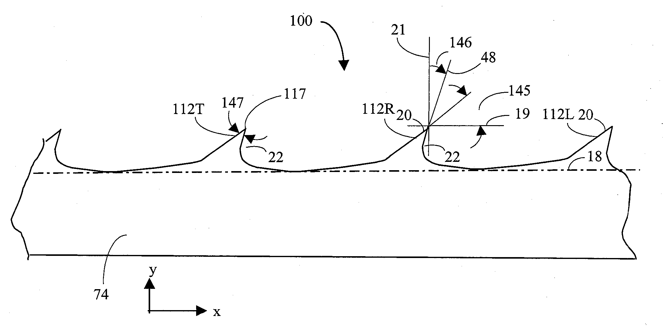
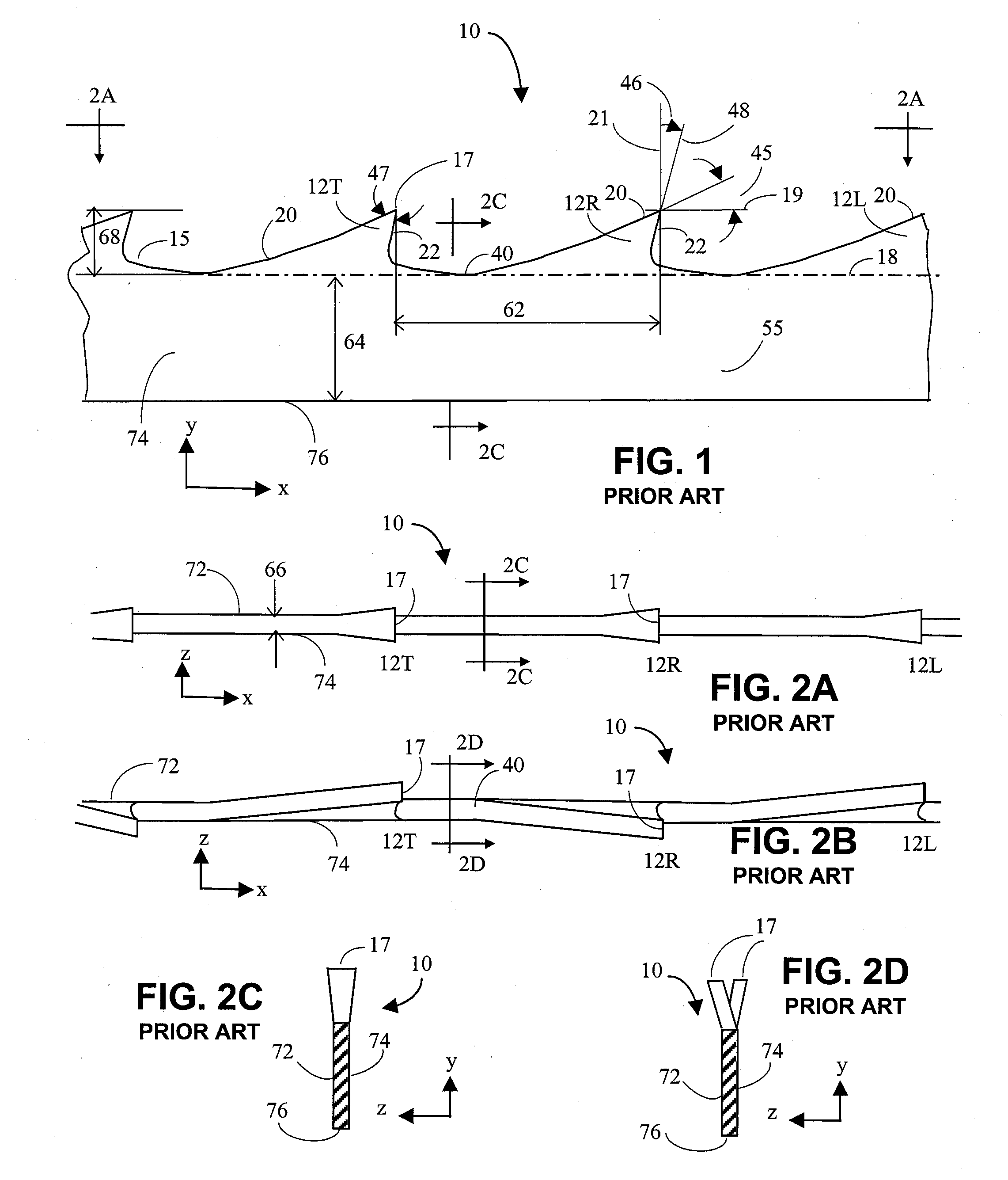
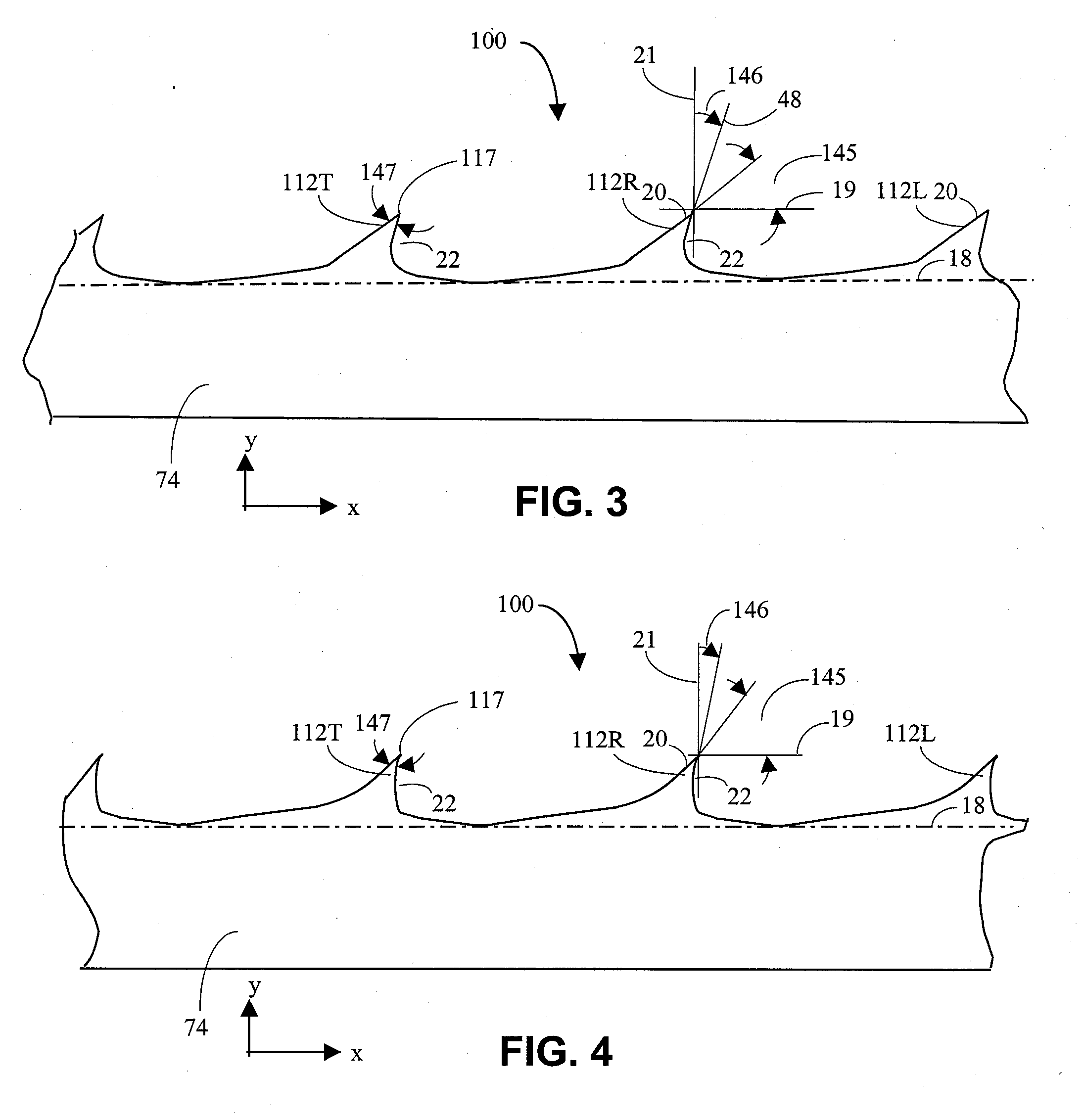
[0027] Referring to FIG. 1 there is shown a conventional blade 10 having teeth 12 for cutting and removing material from a work piece (not shown), such as, for example a log or other piece of wood. In order to cut the work piece, blade 10 moves in the x direction at a desired blade velocity. In some wood cutting processes, the work piece moves in the negative y direction at a desired feed velocity and engages blade 10. In other wood cutting processes, the work piece remains stationary and blade 10 moves at a desired feed velocity in the y direction. The blade velocity and the feed velocity are generally selectable parame...


PUM

PropertyMeasurementUnit
back angleaaaaaaaaaa
hook angleaaaaaaaaaa
back angleaaaaaaaaaa

Abstract

The present disclosure relates to band saw blades often used for cutting wood at a sawmill. A band saw blade has teeth, and at least one tooth has a back angle that is greater than the back angle of conventional band saw blades. The greater back angle results in teeth having a smaller tooth angle so that the teeth make deeper penetration into wood or other materials that are cut by the blade.

Description

CROSS-REFERENCE TO RELATED APPLICATIONS [0001] This application is a continuation-in-part of and claims priority to U.S. Utility patent application Ser. No. 11 / 399,197 entitled “Band Saw Blade” filed on Apr. 6, 2006. This application also claims priority to U.S. Provisional Patent Application No. 60 / 776,634, entitled “Band Saw Blade” filed on Feb. 25, 2006; U.S. Provisional Patent Application No. 60 / 836,190, entitled “Grind Rock for Making Band Saw Blade” filed on Aug. 8, 2006; U.S. Provisional Patent Application No. 60 / 845,672, entitled “Method and Apparatus for Manufacturing Band Saw Blade with Novel Profile” filed on Sep. 19, 2006; and U.S. Provisional Patent Application No. 60 / 885,835 entitled “Band Saw Blade” filed on Jan. 19, 2007. All of the foregoing provisional and non-provisional applications are incorporated by reference herein.FIELD OF THE DISCLOSURE [0002] The present disclosure generally relates to the field of band saw blades for cutting wood and other relatively soft...

Claims


Application Information

Patent Timeline
Patent Type & Authority Applications(United States)
IPC IPC(8): B23D61/12B23D63/00
CPCB23D63/00B23D61/12Y10T83/04Y10T83/9319
Inventor COOK, JAMES TIMOTHYCOOK, STEPHEN OTHNIEL
Owner COOKS SAW MFG
Why Eureka
Try Eureka