

Archery bow sights and archery bows including same
a technology of archery bows and sights, applied in the field of archery, can solve the problems of limiting the archer's view of the target, affecting the flexibility of the archer to easily and quickly change between sight pins, and the level sight gauge may also partially interfere with the view of the targ
- Summary
- Abstract
- Description
- Claims
- Application Information
AI Technical Summary
Benefits of technology
Problems solved by technology
Method used
Image

Examples
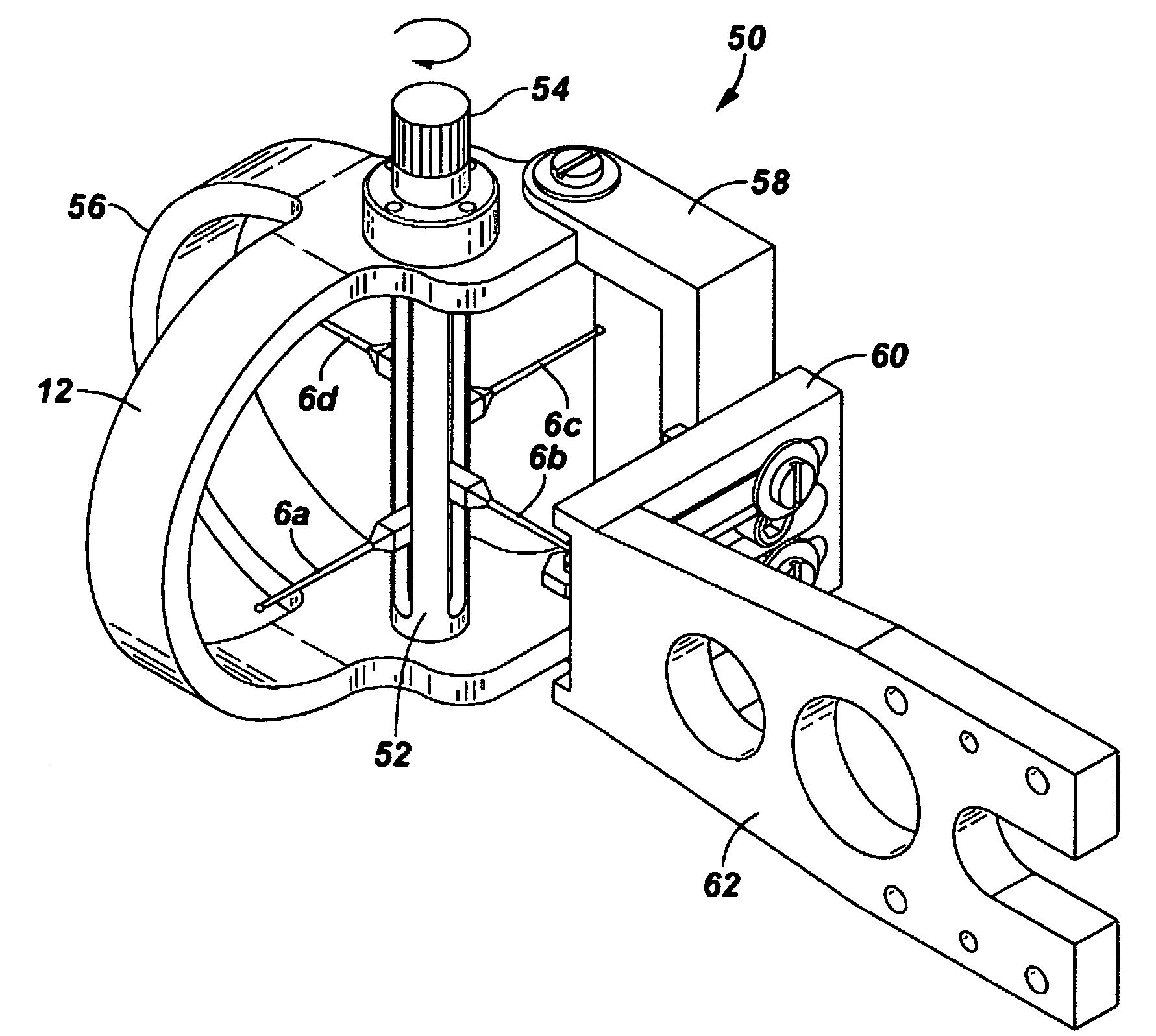
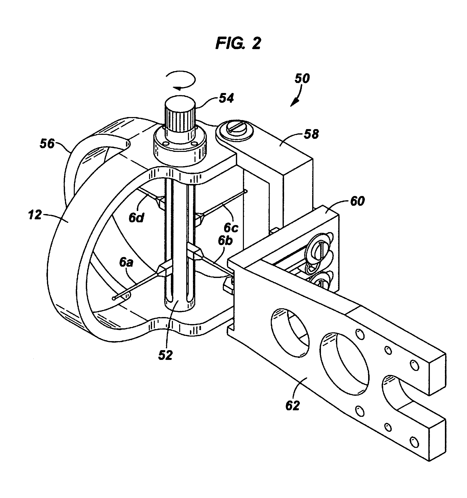
embodiment 50
[0045]FIG. 3 is an exploded perspective view of bow sight 50 of FIG. 2, illustrating more details of construction of this embodiment. Horizontal adjustment block 61 is viewable, having three adjustment holes 63 (illustrated in more detail in FIG. 6) that mate with corresponding lateral slots 64 in attachment 60, along with a nut 65 and cap screw 66. As illustrated in FIG. 6, the two outside holes 63 are threaded, while the middle hole 63 is not in this embodiment. Screw 66 fits inside middle hole 63 in block 61. Nut 65 may slide within a slot 72 in vertical adjustment block 58, allowing block 58 to slide up and down in rails 102 and 104 of block 61, thus allowing vertical adjustment of the bow sight. Screws 68, 70 and washers 67, 69 allow movement of block 60 in a horizontal direction when loosened, providing horizontal adjustment for the bow sight. In embodiment 50, four slots 59 are provided for receiving four sight pin anchors 7. Only two slots are viewable in FIG. 2, and only on...
embodiment 300
[0053] Another aspect of the invention are archery bows incorporating a bow sight of the invention, such as the bow embodiment 300 illustrated schematically in FIG. 11, which comprises conventional components such as eccentrics 302 and 304, aim cables 306 and 308, bow string 310, and bow limbs 312 and 314. Archery bows of this nature also typically include dual line adjustment bolts 316 and 318, a stabilizer bushing 324, a grip 320, a riser 321, and a sight window 322. Sight pins guards 12 and 56 of a bow sight of the invention are illustrated, as well as mounting platform 62, which is secured to sight window 322 using flat head screws or other attachment means, not illustrated in FIG. 11. A cable guard glide 326 and cable guard bar 328, as well as a peep sight 330 complete this embodiment. Those skilled in the art of archery will recognize many variations of components that may still be within the scope of the present invention.
[0054] Archery bows are made by a variety of manufactu...
PUM
 Abstract
Description
Claims
Application Information