Light source apparatus for WDM optical communication and optical communication system

a technology of optical communication and light source apparatus, applied in the field of optical communication system, can solve the problems of non-uniform transmission characteristics of optical signals, degraded utility of wavelengths, and non-uniform output light power, and achieve the effect of reducing or overcoming problems and substantial uniformity in transmission characteristics

Inactive Publication Date: 2007-04-24
SAMSUNG ELECTRONICS CO LTD
View PDF9 Cites 5 Cited by
  • Summary
  • Abstract
  • Description
  • Claims
  • Application Information

AI Technical Summary

Benefits of technology

[0016]The present invention has been made to reduce or overcome the problems incurred in the related art and provides additional advantages, by providing a light source apparatus for WDM optical communication capable of achieving a substantial uniformity in the transmission characteristics of injection light sources at different wavelengths, and an optical communication system using the light source apparatus.

Problems solved by technology

Disadvantageously, the output light power of injection light sources is non-uniform for different wavelengths, thus transmission characteristics of optical signals are non-uniform.
However, utility of wavelengths is degraded.
However, a non-uniformity in insertion loss occurs at different wavelengths due to different filter positions, thereby causing a non-uniformity in output light power. FIG. 2 is a graph depicting insertion loss distribution at different wavelengths according to positions of thin film filters in the thin film filter multiplexer / demultiplexer of FIG. 1.
Although such a non-uniformity in insertion loss at different wavelengths may be eliminated (using an additional process) an increase in insertion loss is incurred in this case.
Furthermore, there is a cost burden, thus, the advantages of the thin film filters compared to gratings disappear.

Method used


Image

  • Light source apparatus for WDM optical communication and optical communication system
  • Light source apparatus for WDM optical communication and optical communication system
  • Light source apparatus for WDM optical communication and optical communication system

Examples


Embodiment Construction

[0029]Now, embodiments of the present invention will be described in detail with reference to the annexed drawings. For the purposes of clarity and simplicity, a detailed description of known functions and configurations incorporated herein will be omitted when it may make the subject matter of the present invention rather unclear.

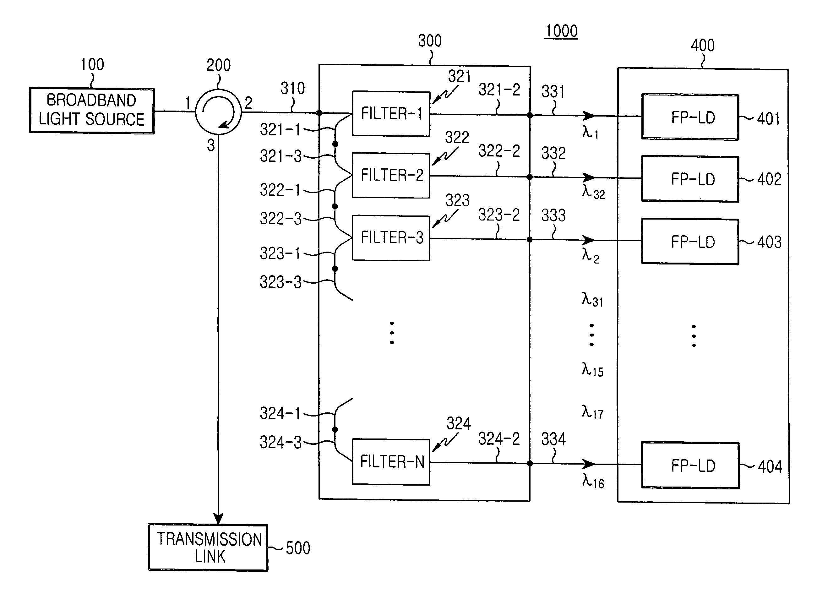
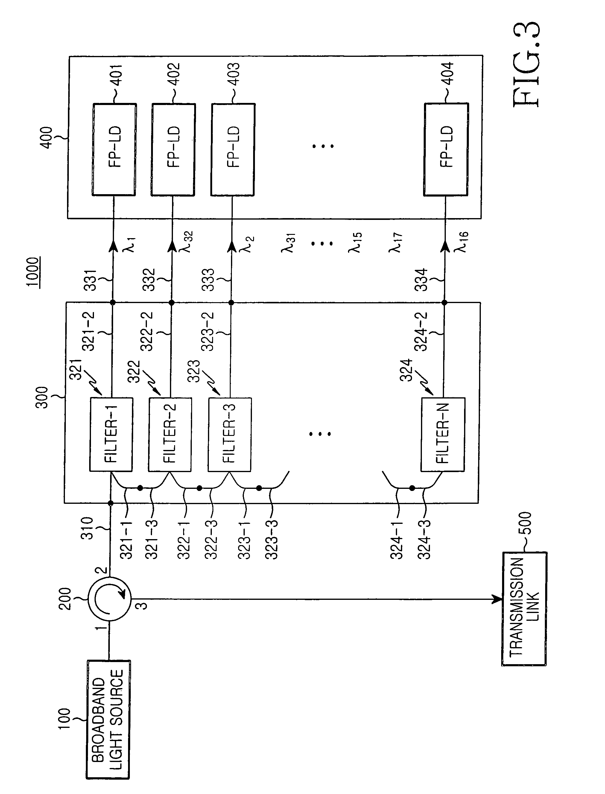
[0030]FIG. 3 is a schematic block diagram illustrating a light source apparatus for WDM optical communication in accordance with an exemplary embodiment of the present invention. As shown in FIG. 3, the light source apparatus for WDM optical communication includes a broadband light source 100, an optical circulator 200, a multiplexer / demultiplexer 300 using optical filters, and N injection light sources 400.

[0031]The broadband light source 100 generates light having a flat power profile over a broad wavelength band ranging from a wavelength λ1 to λn. The broadband light source 100 may be implemented, using an incoherent light source such as an erbium-doped...


PUM


Abstract

A light source apparatus for use with optical communication using external-injection light sources, and an optical communication system using the light source apparatus. The light source apparatus for optical communication includes external-injection light sources, and a multiplexer / demultiplexer. The multiplexer / demultiplexer provides light components spectrum-sliced broadband light from a broadband light source as respective external injection light inputs. The multiplexer / demultiplexer includes a first waveguide to transmit the broadband light and multiplexed light with a plurality of wavelengths, a plurality of second waveguides each to transmit light with an associated one of the wavelengths, and a plurality of optical filters each to pass light with an associated one of the wavelengths and to reflect the remaining wavelengths. The pass wavelength of each optical filter is set such that insertion loss distribution of the optical filters at the wavelengths is similar to a gain distribution of the injection light sources at the wavelengths.

Description

CLAIM OF PRIORITY[0001]This application claims priority to an application entitled “LIGHT SOURCE APPARATUS FOR WDM OPTICAL COMMUNICATION AND OPTICAL COMMUNICATION SYSTEM USING THE SAME,” filed in the Korean Intellectual Property Office on Jul. 7, 2004 and assigned Serial No. 2004-52777, the contents of which are hereby incorporated by reference.BACKGROUND OF THE INVENTION[0002]1. Field of the Invention[0003]The present invention relates to an optical communication system, and more particularly to a light source apparatus for optical communication using external-injection light sources. The present invention also relates to a method for improving transmission characteristics of the light source apparatus for optical communication and an optical communication system.[0004]2. Description of the Related Art[0005]Wavelength division multiplexed (WDM) passive optical networks have been highlighted as the next-generation optical network to provide future broadband communication services. A...

Claims


Application Information

Patent Timeline
Patent Type & Authority Patents(United States)
IPC IPC(8): G02B6/26H04J14/02G02B6/293H04B10/294H04J14/00
CPCH04B10/506H04J14/02H04B10/2581H04B10/00G02B6/12G02B6/02
Inventor SHIN, DONG-JAEHWANG, SEONG-TAEKJUNG, DAE-KWANG
Owner SAMSUNG ELECTRONICS CO LTD
Why Eureka
Try Eureka