Electric Power Plant With Thermal Storage Medium

a technology of thermal storage medium and electric power plant, which is applied in the direction of machines/engines, lighting and heating apparatus, and greenhouse gas reduction. it can solve the problems of inefficiency of previous systems, inability to store energy at high temperatures, and inability to use the bellac patent system to store energy at temperatures exceeding the boiling point of heat transfer fluid

Inactive Publication Date: 2007-09-27
NEW WORLD GENERATION
View PDF8 Cites 40 Cited by
  • Summary
  • Abstract
  • Description
  • Claims
  • Application Information

AI Technical Summary

Benefits of technology

The present invention provides a power plant with a solid heat storage medium that can store and transfer heat to produce electricity. The heat storage medium can be heated to high temperatures and is suitable for producing electricity during peak hours or when the energy source is not producing sufficient electricity. The power plant can also be quickly started up or closed down under controlled conditions.

Problems solved by technology

The technical problem addressed in this patent is the inefficient and inability of previous systems to store energy at high temperatures and the need for a system that can quickly start up again after shutdowns.

Method used


Image

  • Electric Power Plant With Thermal Storage Medium
  • Electric Power Plant With Thermal Storage Medium

Examples


Embodiment Construction

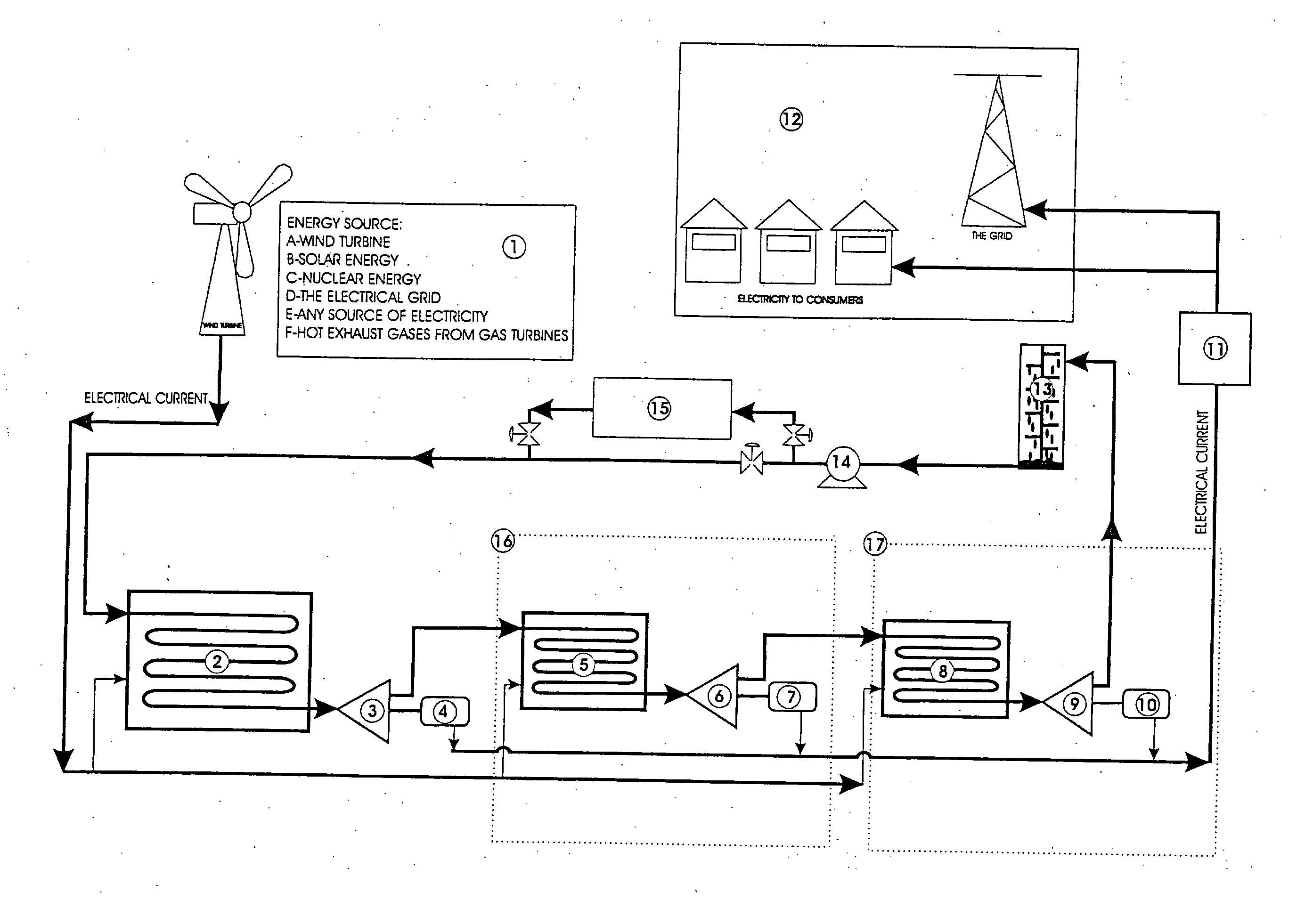
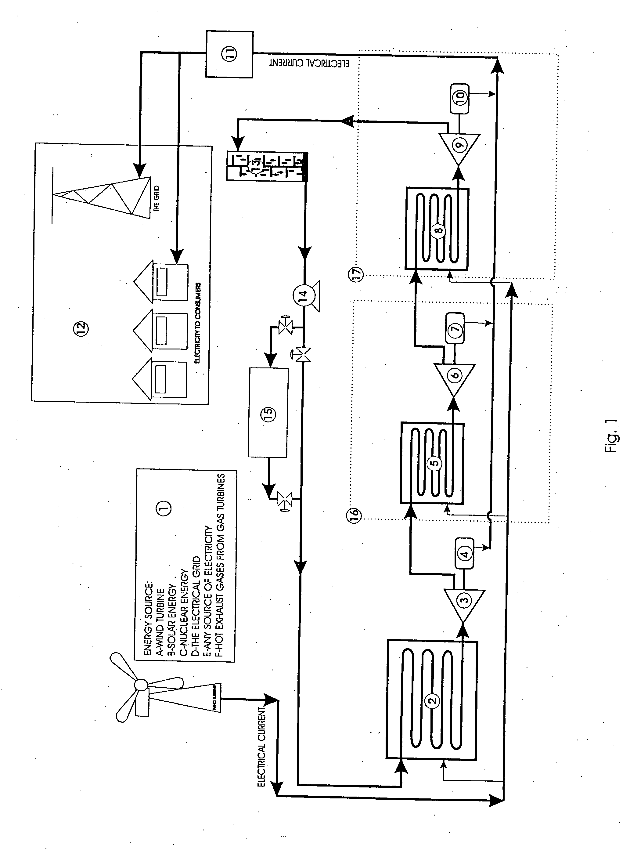
[0011] In FIG. 1, the energy source is a wind turbine 1. The wind turbine powers a first generator(s) (not shown) to produce an electric current. The first generator(s) is (are) located within the wind turbine 1. The electric current passes into a series of heaters (not shown). The heaters are interspersed throughout a solid heat storage medium 2 in a first stage. A channel passes through the heat storage medium 2, which also functions as a heat exchanger. Preferably, the channel passes through the heat storage medium in a serpentine path. When the channel is filled with water, heat is transferred from the heat storage medium to the water. The channel can then be said to be a water line. The heat storage medium is sized and operated at a sufficiently high temperature to convert the water within the water line to steam at an outlet of the heat storage medium 2. The steam enters a steam engine 3 or a steam turbine or any other machinery that is capable of converting steam energy into ...


PUM


Abstract

A power plant uses an energy source (1) to produce electricity in a first generator. The electricity from the first generator provides heat to a solid heat storage medium (2). The solid heat storage medium (2) is a heat exchanger and water is pumped through the solid heat storage medium to receive heat in order to convert the water into steam. The steam is then used to drive a set of second generators (4) to produce electricity. In this way, electricity can be produced using heat from the heat storage medium (2) whether or not the energy source (1) is operable. For example, if the energy source (1) is a wind turbine and the wind is not traveling at sufficient velocity to produce electricity, the heat storage medium can be used to convert water into steam, and reheat steam which is then used to generate electricity in a second generator (4).

Description


Claims


Application Information

Patent Timeline
Owner NEW WORLD GENERATION
Why Eureka
Try Eureka