Actuators

a technology of actuators and actuators, applied in the field of actuators, can solve the problems of increasing the cost and complexity of actuators, the weight of independent lock actuators, and the equipment required to support them

Inactive Publication Date: 2007-09-27
WOODWARD HRT +1
View PDF9 Cites 51 Cited by
  • Summary
  • Abstract
  • Description
  • Claims
  • Application Information

AI Technical Summary

Benefits of technology

[0006]The lock member is preferably displaceable radially. The lock member may be retained in the first position by a second member and the second member may be displaceable axially in response to rotation of the input member. The lock member and linear output member may have cooperating inclined surfaces such that linear movement of the output member applies a radial force to the lock member. The mechanism for converting rotary motion to linear motion includes a lead screw and nut mechanism. The rotary input member is preferably coupled with the lead screw by a lost-motion coaxial drive sleeve, and the drive sleeve preferably connects with the input member by cooperating threads on the input member and the drive sleeve such that rotation of the input member initially causes axial displacement of the drive sleeve before it causes rotation of the drive sleeve and of the lead screw. The drive sleeve may cooperate with a separate, axially-displaceable lock sleeve to effect axial displacement of the lock sleeve when the drive sleeve is displaced axially. The lock sleeve may have an inner surface arranged to engage one end of a radially-displaceable lock member such as to enable or prevent displacement of the lock member.

Problems solved by technology

The use of a separate lock driver actuator increases the cost and complexity of the actuator.
An important disadvantage in aerospace applications is the weight associated with the independent lock actuation and the equipment required to support it.

Method used


Image

  • Actuators
  • Actuators
  • Actuators

Examples


Embodiment Construction

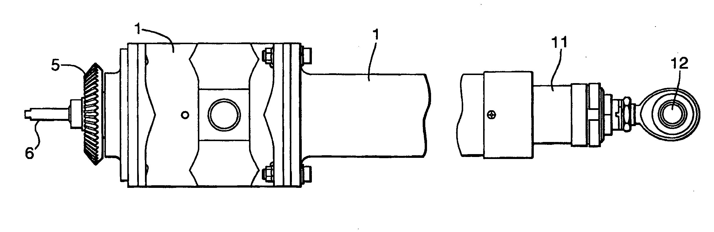
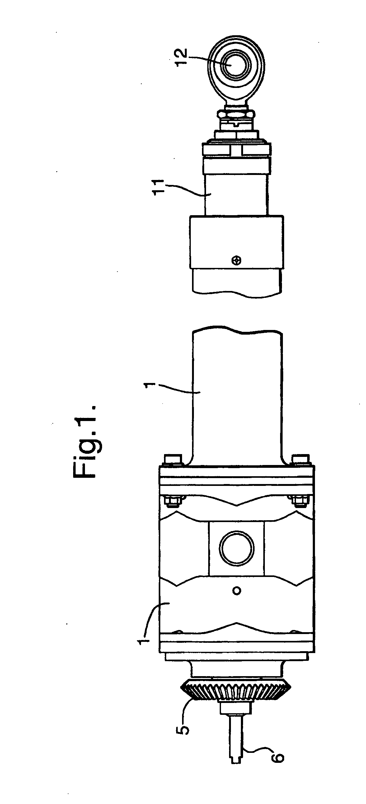
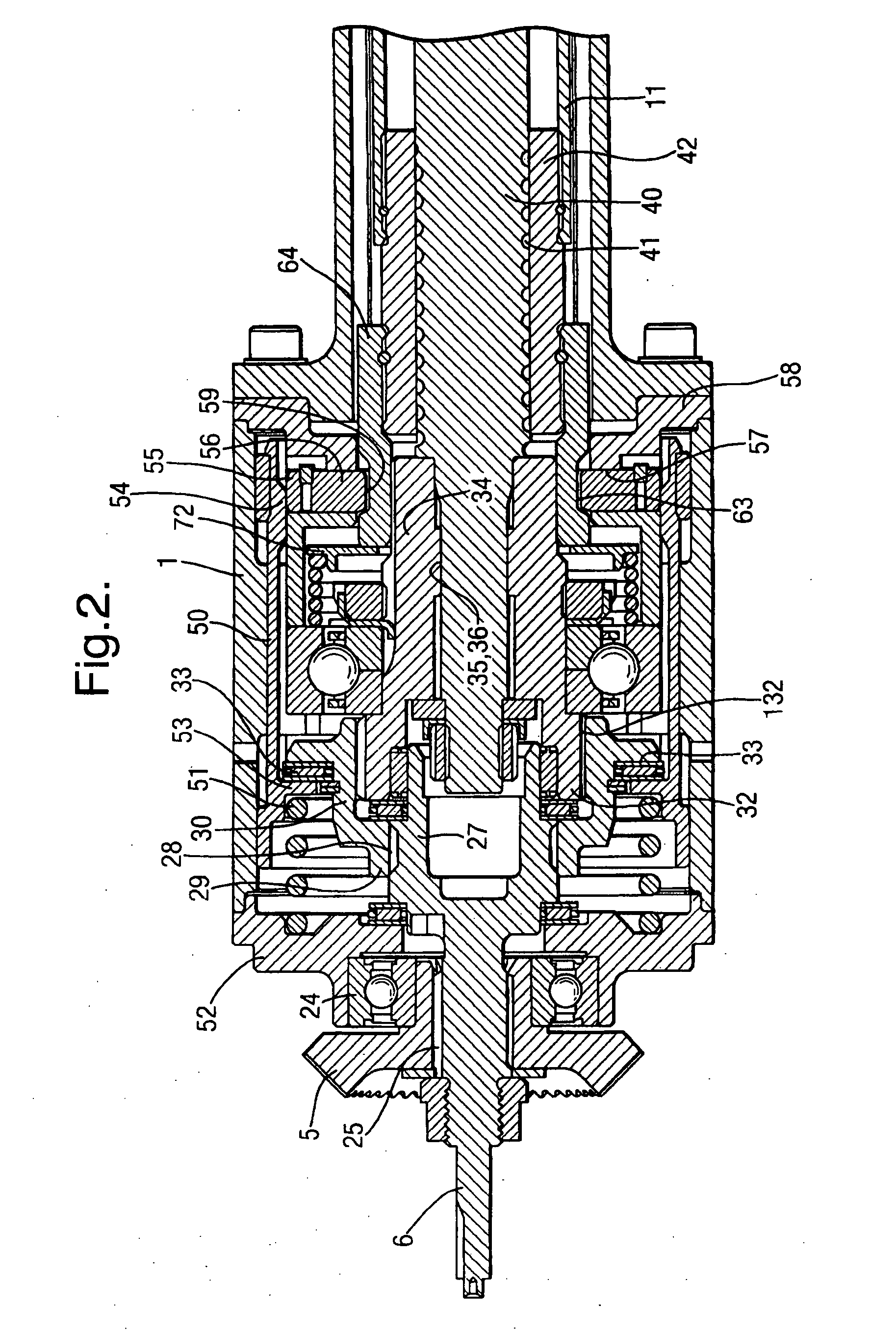
[0017]With reference first to FIGS. 1 and 2, the actuator has an outer casing 1 of generally cylindrical shape and is supported approximately midway along its length by two gimbals for pivoting movement about an axis at right angles to the length of the casing. At the left-hand end of the casing 1, on one side, there is an input drive connection 5 in the form of a bevel gear mounted to the axial drive shaft 6. A lead screw and nut mechanism indicated by the numeral 40 and 42 converts the rotary motion of the axial drive shaft 6 into linear motion of a generally cylindrical ram member 11 so that this is extended out of or retracted into the right-hand end of the casing 1. The ram member 11 has an eye 12 at its far end to which a member to be displaced, such as a door or panel, is attached. When the ram member 11 is fully retracted into the casing 1 it is locked in the retracted position by the mechanism until a rotary drive is applied by via the bevel gear 5 to extend the ram.

[0018]T...


PUM


Abstract

An actuator has an output ram driven to extend and retract by a rotating lead screw. The lead screw is coupled with a rotating input shaft via a lost-motion drive sleeve connected with the input shaft by cooperating threads so that rotation of the drive shaft causes both axial and rotational movement of the drive sleeve. The ram is locked in its retracted position by several radially-extending locking keys, one end of which engage an extension sleeve fixed with the ram and the other end of which are engaged by a lock sleeve. Rotation of the input shaft causes the drive sleeve to move axially and engage the lock sleeve, thereby pulling it to one side and allowing the locking keys to move radially out and disengage the extension sleeve to allow it to extend.

Description

BACKGROUND OF THE INVENTION[0001]This invention relates to actuators.[0002]The invention is more particularly concerned with linear actuators that can be locked in position.[0003]Conventional linear actuators may be driven from a rotary source such as an electric, hydraulic or pneumatic motor. The actuator includes a mechanism to convert the rotary motion from the motor to a linear output motion to translate an external load. The actuator may have a lock mechanism to retain the output ram in a fixed position, usually a retracted position, until power is applied to extend the ram. The lock is sequentially actuated to an unlocked state before the torque necessary to deploy the ram is applied. This is typically accomplished by a solenoid or electric motor mechanically linked to the lock mechanism and is separate from the drive motor that actuates the load. The use of a separate lock driver actuator increases the cost and complexity of the actuator. Separate dedicated actuation commands...

Claims


Application Information

Patent Timeline
Patent Type & Authority Applications(United States)
IPC IPC(8): F16H27/02
CPCB64C13/28B66F3/16Y10T74/18696Y10T74/18704F16H25/2454B64C1/1407
Inventor KOPECEK, JOSEPH THOMAS
Owner WOODWARD HRT
Why Eureka
Try Eureka