Disappearing Plug

Active Publication Date: 2007-09-27
BAKER HUGHES INC
View PDF17 Cites 99 Cited by
  • Summary
  • Abstract
  • Description
  • Claims
  • Application Information

AI Technical Summary

Benefits of technology

[0006] A system allows for sequential treatment of sections of a zone. Access to each portion can be with a sliding sleeve that has a specific internal profile. Pump down plugs can be used that have a specific profile that will make a plug latch to a specific sleeve. Pressure on the plug when latched allows a sequential opening of sleeves while zones already affected that are below are isolated. The pump down plugs have a passage that is initially obstructed by a material that eventually disappears under anticipated well conditions. As a result, when all portions of a zone are handled a flow path is reestablished through the various latched plugs. The plugs can also be blown clear of a sliding sleeve after operating it and can feature a key that subsequently prevents rotation of the plug on its axis in the event it later needs milling out.

Problems solved by technology

The problem with it is that different sized seats are required at specific locations to make the isolation system work and in the end there are some rather small passages through the smallest of the seats even if the balls are floated out that then requires a discrete step of milling out the seat and ball near all but one sliding sleeve.

Method used


Image

  • Disappearing Plug
  • Disappearing Plug
  • Disappearing Plug

Examples


Embodiment Construction

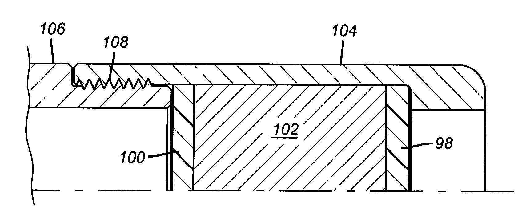
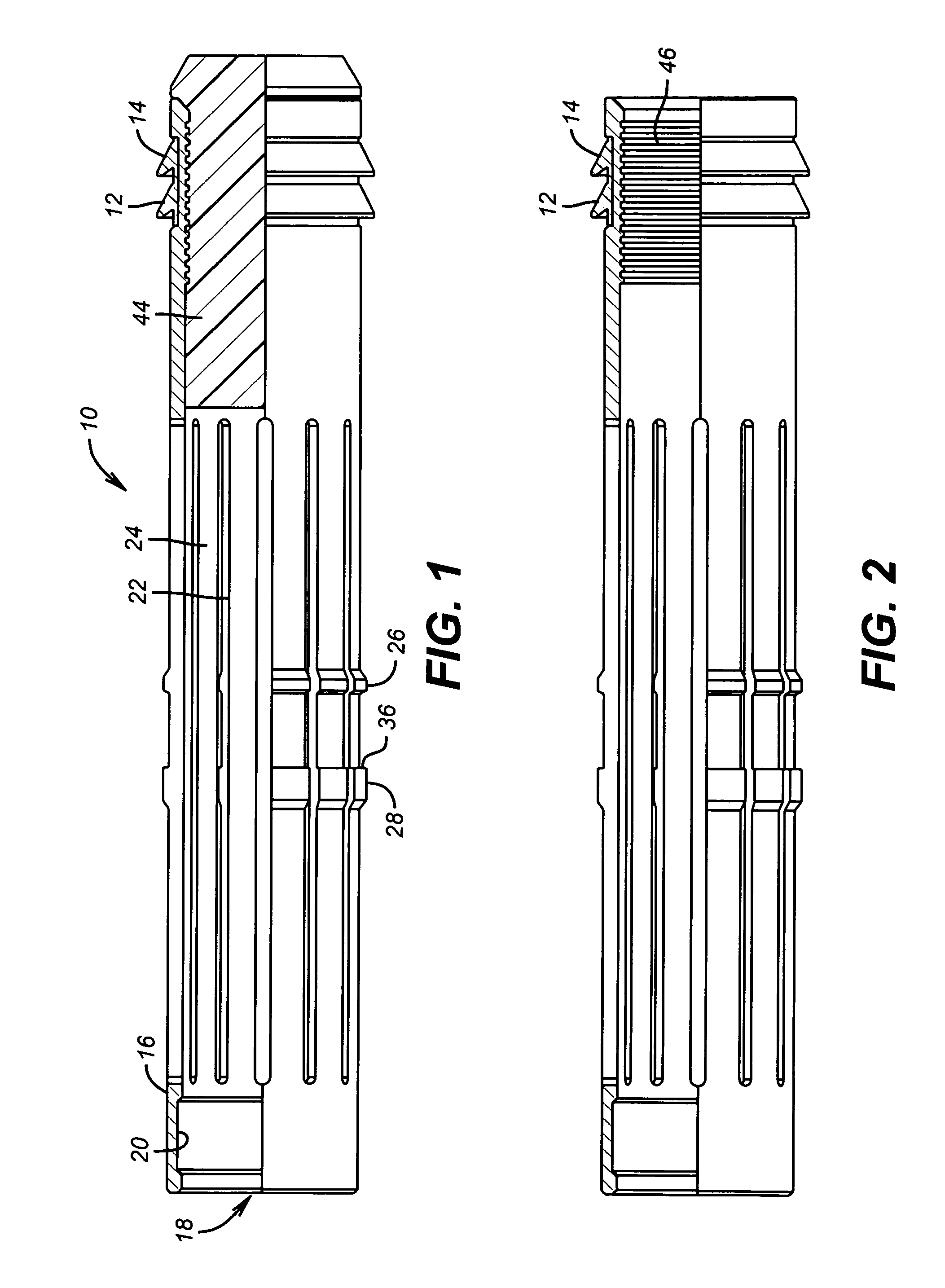
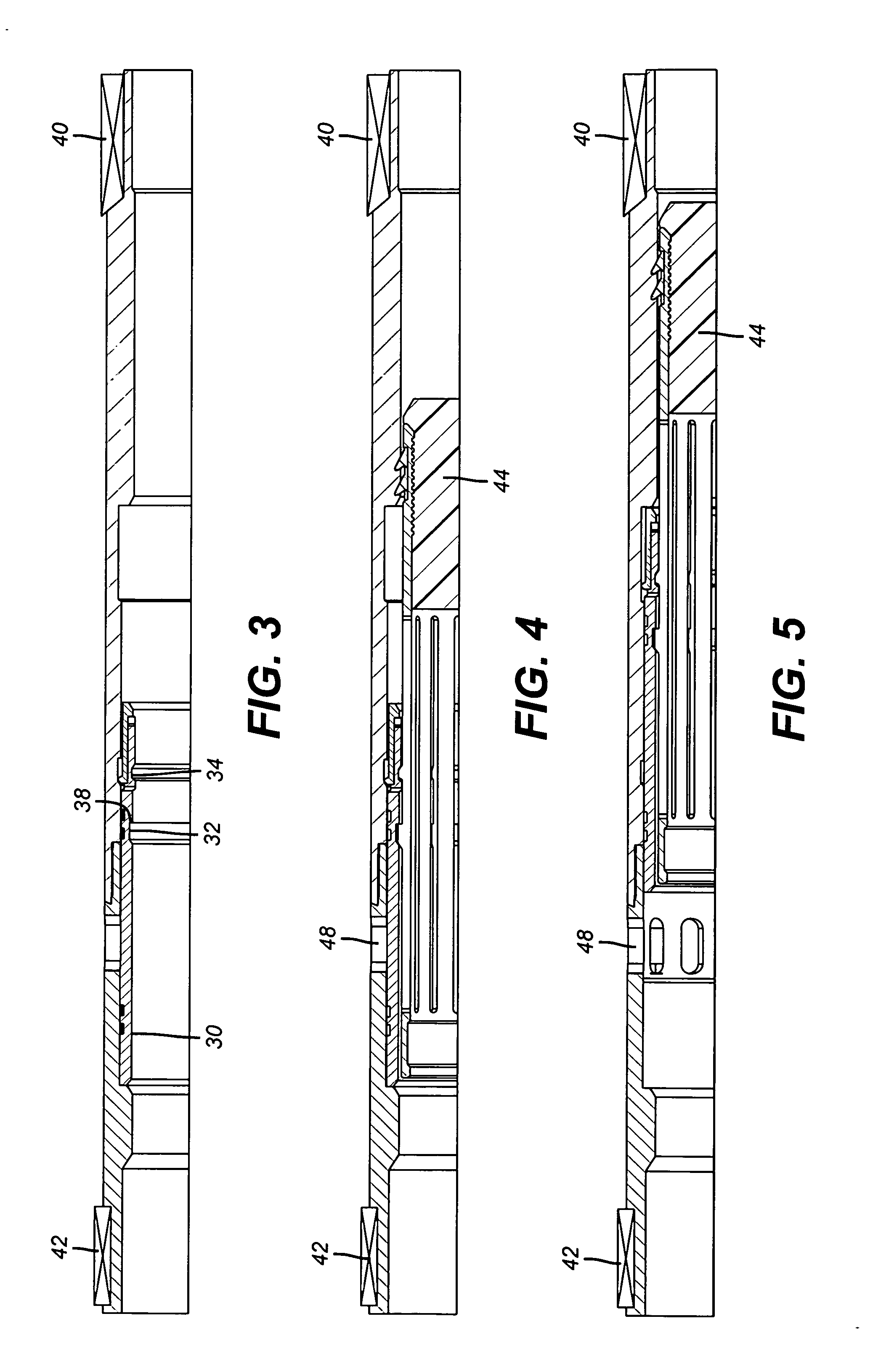
[0023]FIG. 1 shows a typical pump down plug 10 that has wiper seals 12 and 14 to make contact with the surrounding tubular so that it can be pumped down. Although cup seals are shown, other types and quantities of seals can be used. The plug 10 has a tubular body 16 with a through passage 18. Near end 20 is a fishing neck 22 to be used if the plug 10 is to be fished out for any reason. A series of longitudinal grooves 22 define flexible collet fingers 24 that are attached at opposed ends to body 16. Cantilevered fingers can be alternatively used or any other structure that can maintain a cylindrical shape with sufficient strength and still allow flexing. The flexing feature allows the protrusions 26 and 28 to move radially as the plug 10 is pumped downhole. While the preferred plug 10 has seals 12 and 14 the invention envisions a plug 10 that simply is dropped making the use of seals 12 and 14 optional. Looking at FIG. 3, there is a sliding sleeve 30 that has depressions 32 and 34 t...


PUM


Abstract

A system allows for sequential treatment of sections of a zone. Access to each portion can be with a sliding sleeve that has a specific internal profile. Pump down plugs can be used that have a specific profile that will make a plug latch to a specific sleeve. Pressure on the plug when latched allows a sequential opening of sleeves while zones already affected that are below are isolated. The pump down plugs have a passage that is initially obstructed by a material that eventually disappears under anticipated well conditions. As a result, when all portions of a zone are handled a flow path is reestablished through the various latched plugs. The plugs can also be blown clear of a sliding sleeve after operating it and can feature a key that subsequently prevents rotation of the plug on its axis in the event is later needs milling out.

Description

PRIORITY CLAIM [0001] This application is a divisional application claiming priority from U.S. patent application Ser. No. 11 / 388,847, filed on Mar. 24, 2006.FIELD OF THE INVENTION [0002] The field of the invention is completion techniques and more particularly those involving sequential procedures in a zone which need periodic obstruction of the flow bore to conduct the operation and need the flow bore cleared thereafter for production. More specifically the invention focuses on plugs that temporarily block a flow path and then at least in part disappear to allow flow to resume. BACKGROUND OF THE INVENTION [0003] Some completion methods require sequential isolation of adjacent zones in an interval to perform treatments such as fracing. Typically the zones are isolated with packers and in between them there are sliding sleeves that can be selectively opened to provide access. Typically, this assembly is run in to position, and then a ball or plug is pumped down to the bottom which c...

Claims


Application Information

Patent Timeline
Patent Type & Authority Applications(United States)
IPC IPC(8): E21B33/12
CPCE21B23/02E21B33/1212E21B2034/007E21B34/14E21B34/063E21B2200/06
Inventor MURRAY, DOUGLAS J.
Owner BAKER HUGHES INC
Why Eureka
Try Eureka