Treatment apparatus with movable seat for flowback

a technology of flowback and treatment apparatus, which is applied in the direction of fluid removal, well accessories, constructions, etc., can solve the problems of limiting the depth at which plugs can be used, the amount of water it takes, and the inability to easily mill/cut out plugs after being s

Active Publication Date: 2019-08-01
DISRUPTIVE DOWNHOLE TECH LLC
View PDF2 Cites 1 Cited by
  • Summary
  • Abstract
  • Description
  • Claims
  • Application Information

AI Technical Summary

Benefits of technology

[0021]The adaptive seat is held to a smaller diameter for delivery with a tool that features a locating lug for desired alignment of the seat with an intended groove in the inner wall of a tubular. The release tool retracts a cover from the seat allowing its diameter to increase as it enters a groove. Alternatively the seat can be released near the groove and pushed axially in the seat to the groove for fixation. Once in the groove the inside diameter of the string is a support for a blocking object so that sequential treatment of parts of a zone can be accomplished. The blocking object can be removed with pressure, dissolving or disintegration leaving a narrow ledge in the tubular bore from the seat that can simply be left in place. A known setting tool such as an E4#10 from Baker Hughes is modified for seat delivery.

Problems solved by technology

This can be very costly and it also restricts the depth at which plugs can be used.
Plugs themselves can be run out to very long distances; however, such plugs cannot be easily milled / cut out after being set because coil tubing or other drilling / milling means can only extend out so far in a horizontal well.
There is also an issue with the amount of water it takes to pump a plug in a horizontal or directional well to its destination.
Dissolvable plugs and balls are available, but conventional technology is not reliable.
A portion of the balls / plugs dissolve, but often they don't completely dissolve and they end up causing a restriction in the wellbore.
This negates the benefits of running the dissolvable plug in the first place.

Method used


Image

  • Treatment apparatus with movable seat for flowback
  • Treatment apparatus with movable seat for flowback
  • Treatment apparatus with movable seat for flowback

Examples


Embodiment Construction

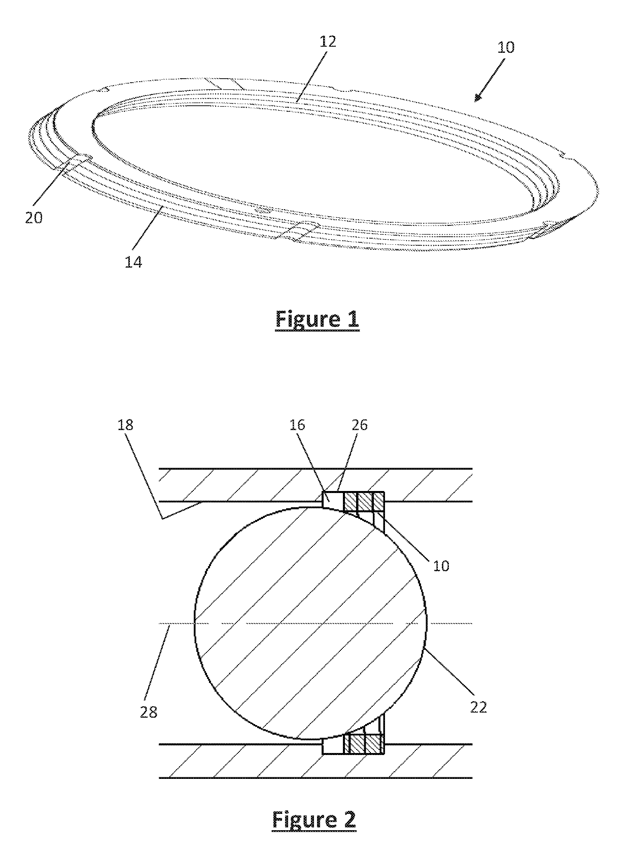
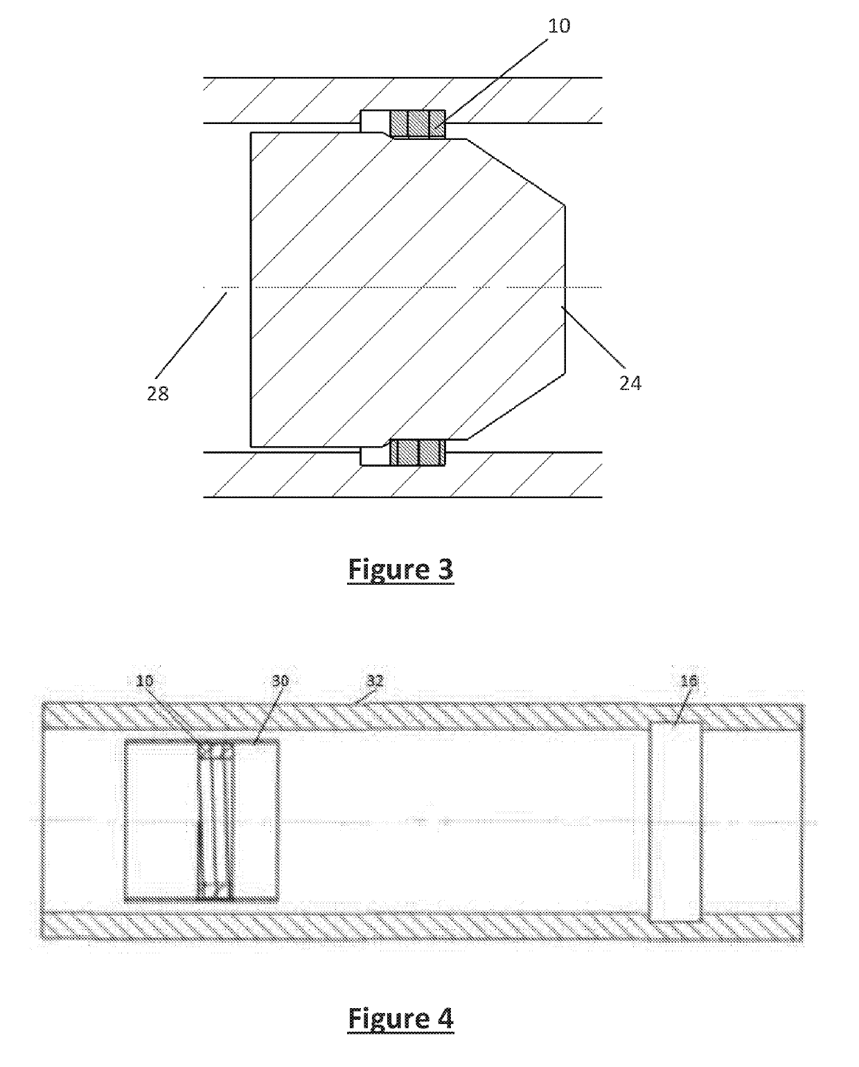
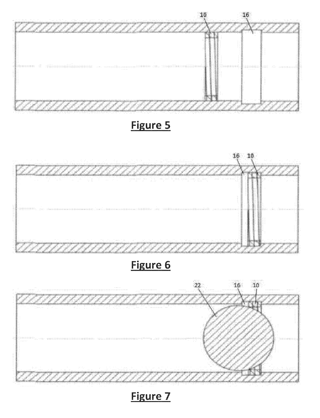
[0071]Referring to FIG. 1 a round shaped adaptive seat 10 is illustrated. It is preferably a continuous coil of preferably flat material that presents an inner surface 12 and an outer surface 14. Preferably surfaces 12 and 14 are aligned for each winding when the adaptive seat 10 is allowed to relax in a retaining groove or recess 16 located in a tubular such as casing or liner or sub 18. Alternatively the outer surface 14 can have surface treatment or texture to bite into or penetrate into the tubular wall when allowed to relax into contact with the tubular wall for support of an object such as ball 22 or dart 24 by resisting shear stress transmitted to adaptive seat 10. Since the seat 10 is delivered compressed to a smaller diameter there can optionally be notches 20 in outer surface 14 to reduce the force needed to reduce the diameter of the seat 10 for running in. Notches 20 also reduce the stress in the adaptive seat. Optionally notches such as 20 can also be on inside surface ...


PUM


Abstract

A coiled adaptive seat is held to a smaller diameter for delivery with a tool that features a locating lug for desired alignment of the seat with an intended groove in the inner wall of a tubular. The release tool retracts a cover from the seat allowing its diameter to increase as it enters a groove. Alternatively the adaptive seat is released near the groove and pushed axially in the string to the groove for fixation. Once in the groove the inside diameter of the string is a support for a blocking object so that sequential treatment of parts of a zone can be accomplished. The blocking object is removed with pressure, dissolving, milling or disintegration leaving a narrow ledge in the tubular bore from the seat that can simply be left in place or milled as well. An E4#10 from Baker Hughes is modified for adaptive seat delivery.

Description

RELATED APPLICATIONS[0001]This Application claims the benefit of U.S. Provisional Application No. 62 / 618,220 filed on Jan. 17, 2018 and U.S. Provisional Application No. 62 / 618,233 filed on Jan. 17, 2018, both of which are incorporated herein as if fully set forth.FIELD OF THE INVENTION[0002]The field of the invention is a barrier support used in sequential formation treatment and more particularly barrier supports that are energized by intrinsic potential energy for fixation in a tubular string to receive an object for isolating already treated zones below that are originally fracked or zones below that have been re-fractured where the drift dimension of the support is large enough that removal of the support is not necessary. More particularly, the present invention pertains to a method and apparatus for permitting flow back of fluid and / or other wellbore barriers used in connection with said barrier support.BACKGROUND OF THE INVENTION[0003]Currently conventional frac plugs have to...

Claims


Application Information

Patent Timeline
Patent Type & Authority Applications(United States)
IPC IPC(8): E21B33/12E21B23/02
CPCE21B33/1208E21B23/02E21B43/26E21B34/14E21B43/12E21B2200/04E21B34/142E21B34/16E21B34/10
Inventor CROW, STEPHEN L.FROST, CLINT
Owner DISRUPTIVE DOWNHOLE TECH LLC
Why Eureka
Try Eureka