Medium feeding apparatus and image forming apparatus

Inactive Publication Date: 2007-09-27
OKI DATA CORP
View PDF2 Cites 25 Cited by
  • Summary
  • Abstract
  • Description
  • Claims
  • Application Information

AI Technical Summary

Benefits of technology

[0007]With such an arrangement, the auxiliary member is disposed on the boundary between the first placing unit an

Problems solved by technology

In such a case, during the setting of the recording sheets on the tray, the recording sheet may be caught in the opening, step or gap, so that the bending, buckling or breakage of the re

Method used


Image

  • Medium feeding apparatus and image forming apparatus
  • Medium feeding apparatus and image forming apparatus
  • Medium feeding apparatus and image forming apparatus

Examples


embodiment 1

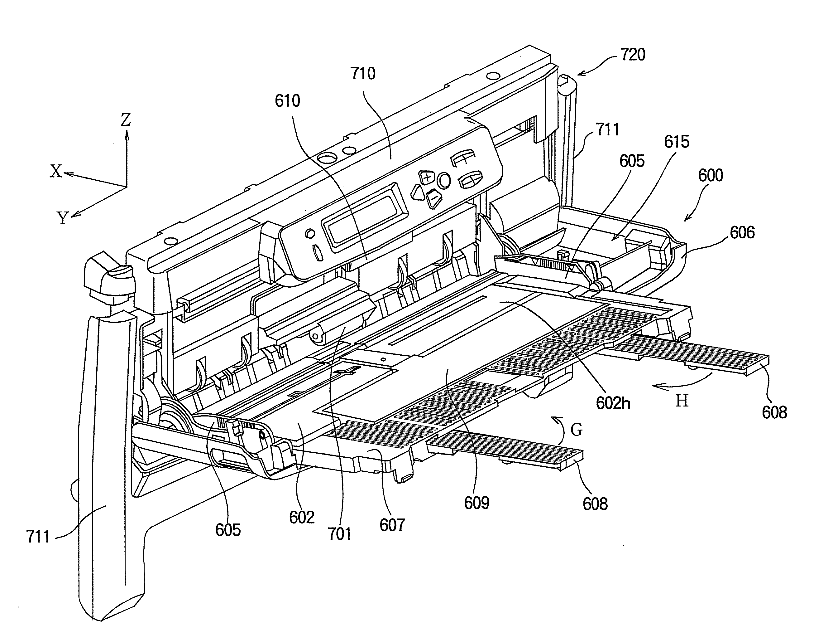
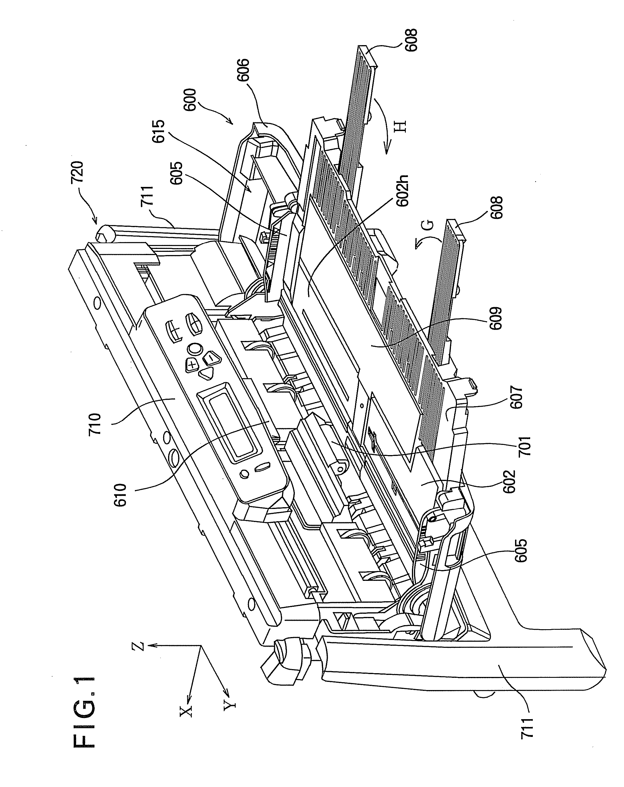
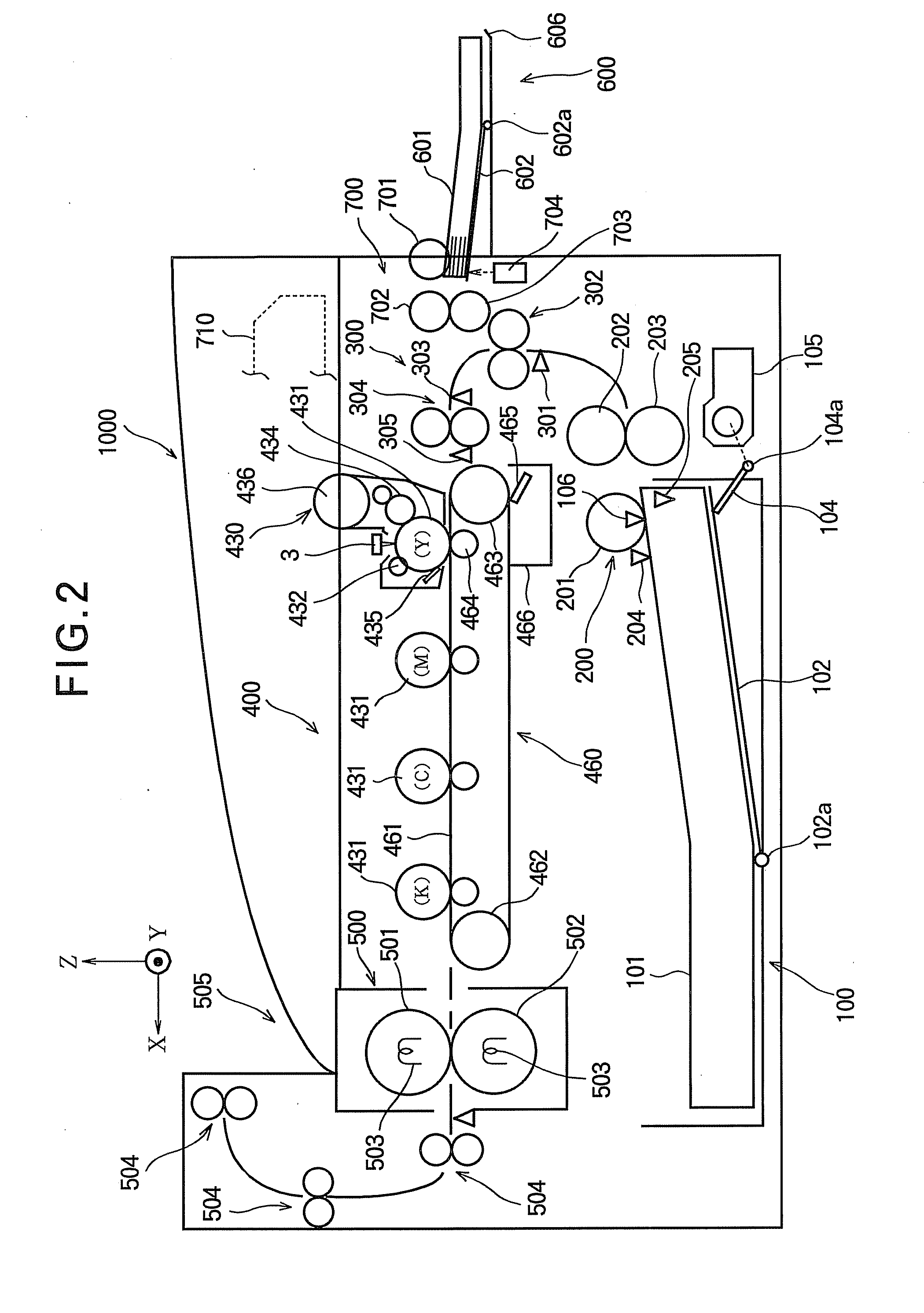
[0032]FIG. 1 is a perspective view showing an outer shape of a medium feeding apparatus according to Embodiment 1 of the present invention. FIG. 2 is a schematic view showing a main part of an image forming apparatus using the medium feeding apparatus according to Embodiment 1 of the present invention.

[0033]First, the image forming apparatus shown in FIG. 2 will be described.

[0034]The image forming apparatus 1000 shown in FIG. 2 has a configuration of, for example, an electrophotographic color printer. In FIG. 2, a sheet supply tray 100 is detachably attached to the image forming apparatus 1000. The sheet supply tray 100 stores recording sheets (i.e., media) 101 stacked therein. In the sheet supply tray 100, a sheet placing plate 102 is rotatably supported by a supporting shaft 102a. A half or more of the stack of the recording sheets 101 on a sheet delivery side is placed on the sheet placing plate 102. A not shown guide member is provided in the sheet supply tray 100, which define...

embodiment 2

[0076]FIG. 7A is a simplified view showing a relationship among an outer cover portion 626, the sheet placing plate 602 (the main tray), the first auxiliary tray 607 and an auxiliary placing plate 629 of a sheet supply tray when assembled according to Embodiment 2 of the present invention.

[0077]The medium feeding apparatus employing this sheet supply tray is mainly different from the medium feeding apparatus 720 (FIG. 1) according to Embodiment 1 in the mounting structure of the auxiliary placing plate 629 shown in FIG. 7A. The components of the medium feeding apparatus employing this sheet supply tray that are the same as those of the above described medium feeding apparatus 720 of Embodiment 1 are assigned the same reference numerals or omitted in drawings, and duplicate explanation will be omitted. The description will be emphasized on the difference.

[0078]In a main placing portion 661 of the sheet supply tray of Embodiment 2 shown in FIG. 7A, the structures of the rotation suppo...

embodiment 3

[0091]FIG. 11A is a simplified view showing a relationship among an outer cover 636, the sheet placing plate (the main tray) 602, the first auxiliary tray 607 and an auxiliary placing sheet 639 of a sheet supply tray when assembled according to Embodiment 3 of the present invention.

[0092]The medium feeding apparatus employing this sheet supply tray is mainly different from the medium feeding apparatus 720 according to Embodiment 1 in that the auxiliary placing sheet 639 shown in FIG. 11A is used in stead of the auxiliary placing plate 609 (FIG. 3). The components of the medium feeding apparatus employing this sheet supply tray that are the same as those of the medium feeding apparatus 720 according to Embodiment 1 are assigned the same reference numerals or omitted in drawings, and duplicate explanation will be omitted. The description will be emphasized on the difference.

[0093]In a main placing portion 665 of the sheet supply tray shown in FIG. 11A, the structures of the rotation s...


PUM


Abstract

A medium feeding apparatus includes a main body, and a medium placing unit at least a part of which can be housed in the main body. The medium placing unit includes a first placing unit held by the main body in such a manner that the first placing unit is shiftable between a housed position where at least one of the first placing unit is housed in the main body and a placing position where the medium can be placed on the first placing unit, a second placing unit has a first shifting condition where the medium can be placed on the first and second placing units and a second shifting condition where the second placing unit is overlapped with the first placing unit, and an auxiliary member disposed on a boundary between the first placing unit and the second placing unit when the second placing unit is in the first shifting condition.

Description

BACKGROUND OF THE INVENTION[0001]This invention relates to a medium feeding apparatus having a medium placing portion, and relates to an image forming apparatus having the medium feeding apparatus and forming an image on a recording medium.[0002]In a conventional sheet supply tray or sheet ejection tray, an openable main tray is provided on a side, front or rear surface of a main body of an image forming apparatus, and a plurality of slidable or foldable auxiliary trays are provided on the main tray. The main tray is configured to have a length corresponding to a regular sized recording medium of a standard length. The auxiliary tray is configured to have a standard length when the auxiliary tray is drawn from the main tray.[0003]Recently, in accordance with the downsizing of the medium feeding apparatus, the shape of the tray tends to be determined to avoid interference with a protrusion such as an operation panel and a locking member for a cover. Therefore, when the folded auxilia...

Claims


Application Information

Patent Timeline
IPC IPC(8): B65H5/26B65H3/44
CPCB41J13/103B65H1/04B65H2405/324B65H2405/111646B65H2405/111643
Inventor MURAKAMI, TATSUYA
Owner OKI DATA CORP
Why Eureka
Try Eureka