Display rotation apparatus

Inactive Publication Date: 2007-09-27
SAMSUNG ELECTRO MECHANICS CO LTD
View PDF6 Cites 7 Cited by
  • Summary
  • Abstract
  • Description
  • Claims
  • Application Information

AI Technical Summary

Benefits of technology

[0017]The first motor part and the second motor part may respectively include a motor and a rotary part, where the rotary part may include a clutch unit coupled with a driving shaft, and a driven shaft in contact with the clutch unit, with the driving force of the motor smaller than the frictional force between the driven shaft and the clutch unit.
[0018]The frictional force between the driven shaft and the clutch uni

Problems solved by technology

However, when the TV is fixed, a clear view of the TV may not be obtained when a viewer moves to a different position.
The conventional wall-mounted-type TV has difficulty in changing directions, because it h

Method used


Image

  • Display rotation apparatus
  • Display rotation apparatus
  • Display rotation apparatus

Examples


Example

[0027]The display rotation apparatus according to certain embodiments of the invention will be described below in more detail with reference to the accompanying drawings. In the description with reference to the accompanying drawings, those components are rendered the same reference number that are the same or are in correspondence, regardless of the figure number, and redundant explanations are omitted.

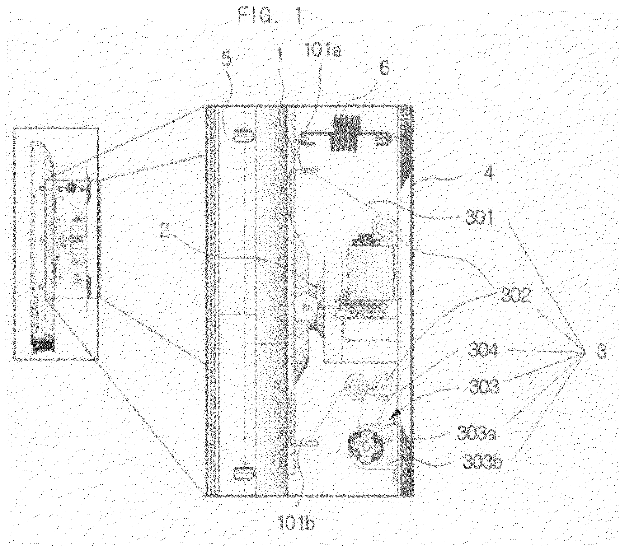
[0028]FIG. 1 is a side view of a display rotation apparatus according to a first disclosed embodiment of the invention. Referring to FIG. 1, a movable body 1, connecting parts 101a, 101b, a universal joint 2, a driving part 3, a tension member 301, roller members 302, a first motor part 303, a motor 303b, a slip pulley 303a, a tension controlling device 304, a support 4, a display 5, and an elastic body 6 are illustrated.

[0029]The movable body 1 may be coupled with the display 5 as one body. The movable body 1 is coupled with the support 4 by way of the universal joint 2. The Movable...


PUM


Abstract

The present invention relates to a display rotation apparatus. The present invention provides a display rotation apparatus, including a support, a universal joint coupled to the support, a movable body coupled to the universal joint, a driving part coupled to the movable body for rotating the movable body about the universal joint.

Description

CROSS-REFERENCE TO RELATED APPLICATIONS[0001]This application claims the benefit of Korean Patent Application No. 10-2006-0027464 filed with the Korean Intellectual Property Office on Mar. 27, 2006, the disclosure of which is incorporated herein by reference in its entirety.BACKGROUND[0002]1. Technical Field[0003]The present invention relates to a display rotation apparatus.[0004]2. Description of the Related Art[0005]The flat panel display, such as an LCD, PDP, or LED, applied to a TV set or monitor has the advantage of efficiently using a narrow space and is thus replacing the Braun tube TV or monitor, with demands for the flat panel display expected to continually increase in the future. In particular, the flat type LCD or the PDP-applied TV are referred to as a ‘wall mounted type TV’, and are used fixedly adhered to the wall. When viewing the wall mounted type TV adhered to the wall in this way, the screen is seen the widest when the TV is located in front of the viewers.[0006]H...

Claims


Application Information

Patent Timeline
IPC IPC(8): G09G5/00
CPCF16M11/06F16M11/10F16M2200/041F16M11/38F16M13/02F16M11/18H04N5/66H04N5/64
Inventor CHOI, DONG-WONLEE, CHIL-SUNGPARK, KYOUNG-SHINKIM, JAE-KYUNG
Owner SAMSUNG ELECTRO MECHANICS CO LTD
Why Eureka
Try Eureka