Line of sight detection apparatus

a detection apparatus and sight technology, applied in the field of sight detection apparatus, can solve the problems of inability to reduce errors in every driver, complicated procedures, etc., and achieve the effects of preventing from being distracted, improving accuracy, and improving reliability of calibration

Inactive Publication Date: 2007-09-27
HONDA MOTOR CO LTD
View PDF4 Cites 7 Cited by
  • Summary
  • Abstract
  • Description
  • Claims
  • Application Information

AI Technical Summary

Benefits of technology

[0013]According to the above line of sight detection apparatus, the reliability of the calibration can be improved.
[0014]As explained above, according to the line of sight detection apparatus of the present invention, the precise calibration can be operated in accordance with the series of driving operations by the driver easily and efficiently. Therefore, the driver can be prevented from being distracted by the calibration.
[0015]In addition, according to the line of sight detection apparatus of the present invention, the reliability of the calibration can be improved.

Problems solved by technology

Therefore, when a plurality of drivers alternate, complicated procedures would be required since the calibration operation is needed for each alternation.
Furthermore, errors which occur in every driver cannot be reduced when calibrating by the calibration value which is statistically calculated.

Method used


Image

  • Line of sight detection apparatus
  • Line of sight detection apparatus
  • Line of sight detection apparatus

Examples


Embodiment Construction

[0019]Below, a line of sight detection apparatus according to one embodiment of the present invention will be explained referring to the attached drawings.

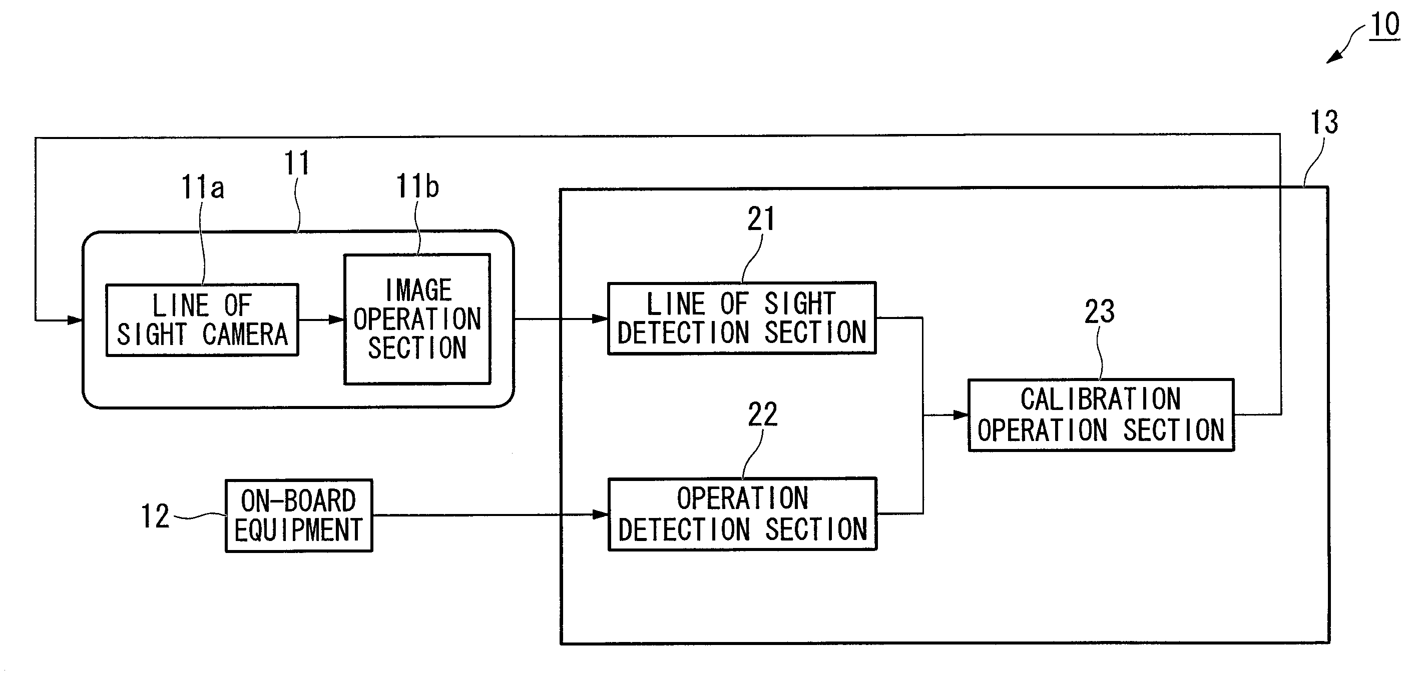
[0020]A line of sight detection apparatus 10 of the present embodiment is, as shown in FIG. 1 for example, constituted from an eyeball sensor 11, an on-board equipment 12, and a control device 13.

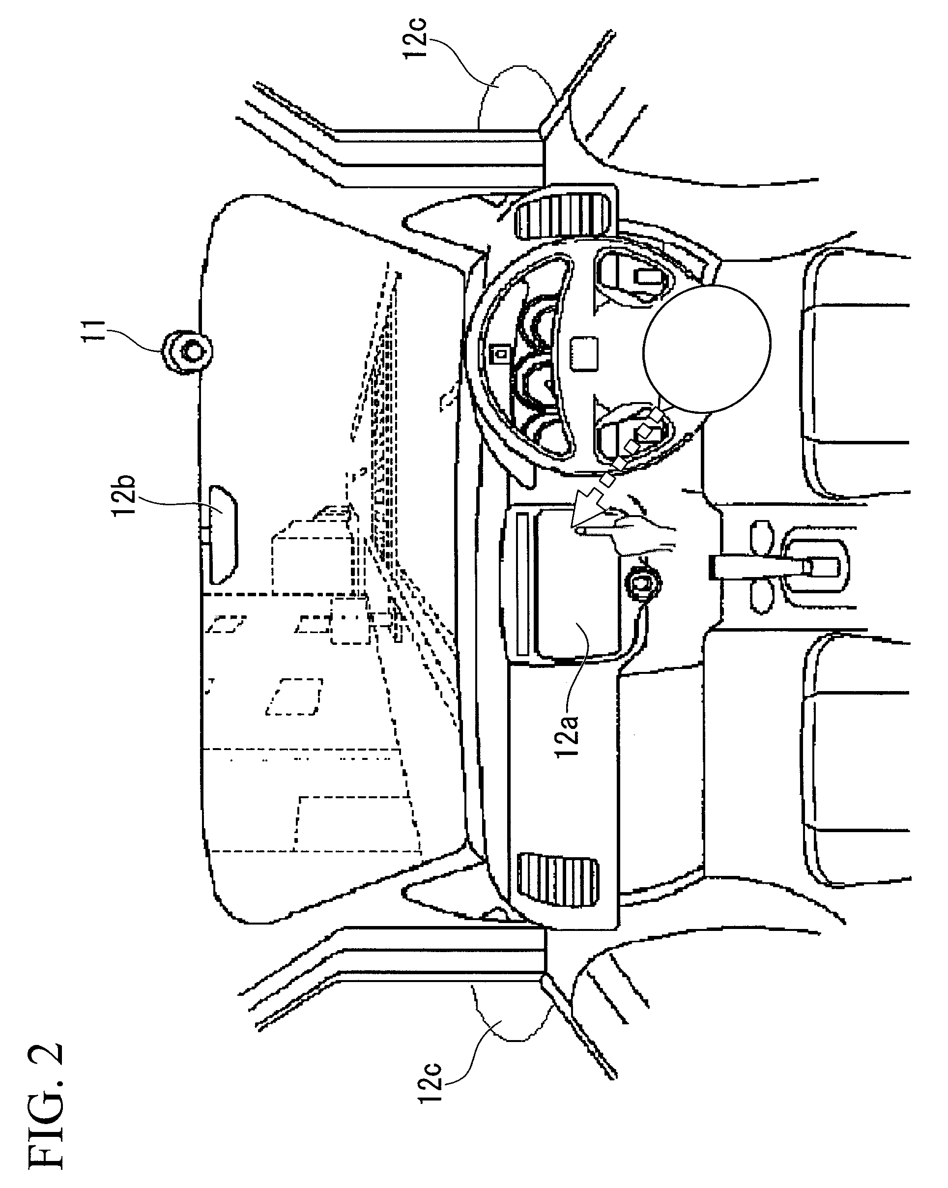
[0021]The eyeball sensor 11 is, as shown in FIG. 2 for example, equipped at a position proximal to a rear view mirror in a compartment toward the driver's side or the like, that is, a position at least where an image of the eyeball of the driver is capturable. The eyeball sensor 11 is constituted from, for example, an eyeball camera (line of sight camera) 11a including a CCD camera, a CMOS camera or the like capturable in a visible light radiation area and an infrared radiation and an eyeball image operation section 11b.

[0022]The eyeball camera 11a captures a visible light radiation reflected from the face or the eyeball of the occupant ...


PUM


Abstract

A line of sight detection apparatus includes: a line of sight detection device which detects the line of sight of an occupant; an operation detection device which detects the operation of on-board equipment by the occupant; and a calibration device which calibrates a detection value of the line of sight detection device based on the operation of the on-board equipment by the occupant which is detected by the operation detection device and position data of the on-board equipment.

Description

BACKGROUND OF THE INVENTION[0001]1. Field of the Invention[0002]This invention is related to a line of sight detection apparatus.[0003]Priority is claimed on Japanese Patent Application No. 2006-085905, filed Mar. 27, 2006, the contents of which are incorporated herein by reference.[0004]2. Description of Related Art[0005]Conventionally, an apparatus which detects the line of sight of a vehicle driver based on, for example, a retinal reflection image, a corneal reaction image, and a pictorial image of the face of the vehicle driver is known (e.g., refer to Japanese Unexamined Patent Application, First Publication No. H08-297019).[0006]In the abovementioned apparatus according to one example of the prior art, some calibration methods to calibrate the detected line of sight are known. For example, the calibration is operated by detecting the line of sight in a state of a driver gazes at a predetermined designated position, or by using calibration value which is statistically calculate...

Claims


Application Information

Patent Timeline
Patent Type & Authority Applications(United States)
IPC IPC(8): A61B3/14
CPCA61B3/113G06V40/19G06V20/597
Inventor KIMATA, AKIHITOTAKAHASHI, AKIO
Owner HONDA MOTOR CO LTD
Why Eureka
Try Eureka