Plug connection adapter

Active Publication Date: 2007-09-27
ERNI PRODION GMBH
View PDF7 Cites 0 Cited by
  • Summary
  • Abstract
  • Description
  • Claims
  • Application Information

AI Technical Summary

Benefits of technology

[0037]The larger cross-section of the contact pins 17 in the area between the first and the second header shrouds 16a, 16b increases the mechanical stability of the plug connection adapter 10 according to the invention. Further, the larger cross-section of the contact pins 17 contributes toward achieving a low ohmic resistance. In addition, the larger cross-section may reduce the inductive reactance, especially in the case of a rectangular cross-section. The illustrated embodiment is based on a rectangular cross-sect

Problems solved by technology

The fact that the second plug-in connector for printed-wiring boards is missing on the second printed-wiring board on the one hand saves the costs of the second plug-in connector for printed-wiring boards, while restricting on the other hand the mounting conditions for the second printed-wiring board, relative to the first printed-wiring board.
The exposed contact pins may easily produce short circuits between t

Method used


Image

  • Plug connection adapter
  • Plug connection adapter
  • Plug connection adapter

Examples


Example

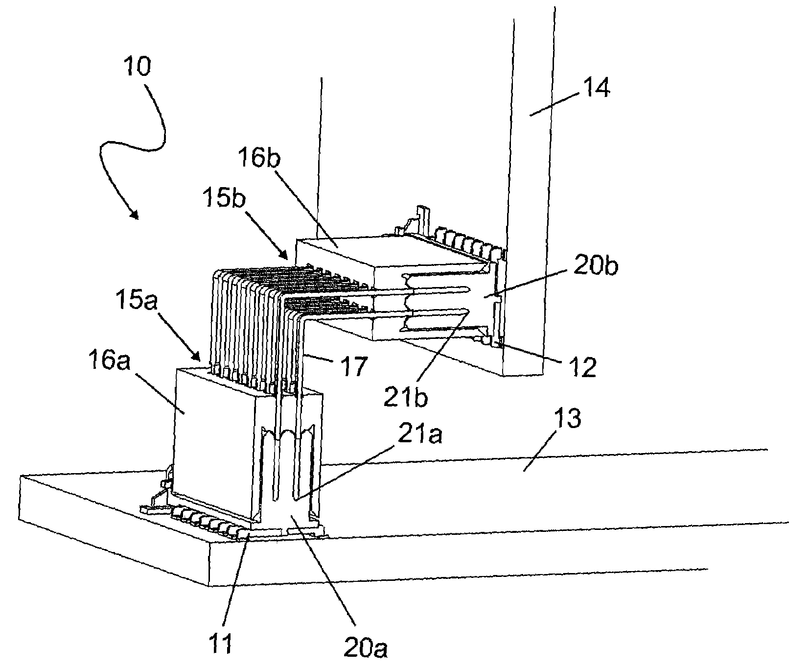
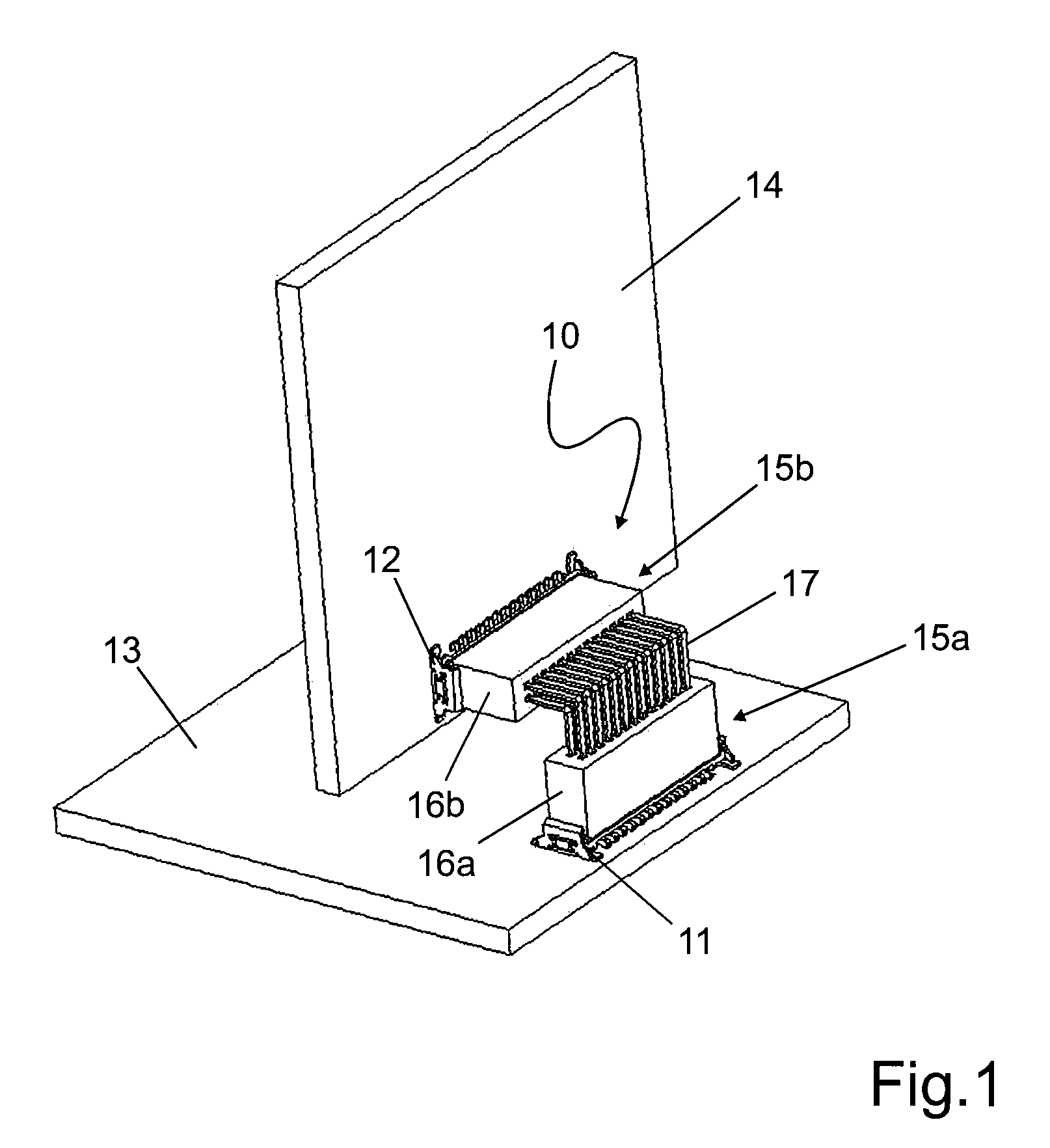
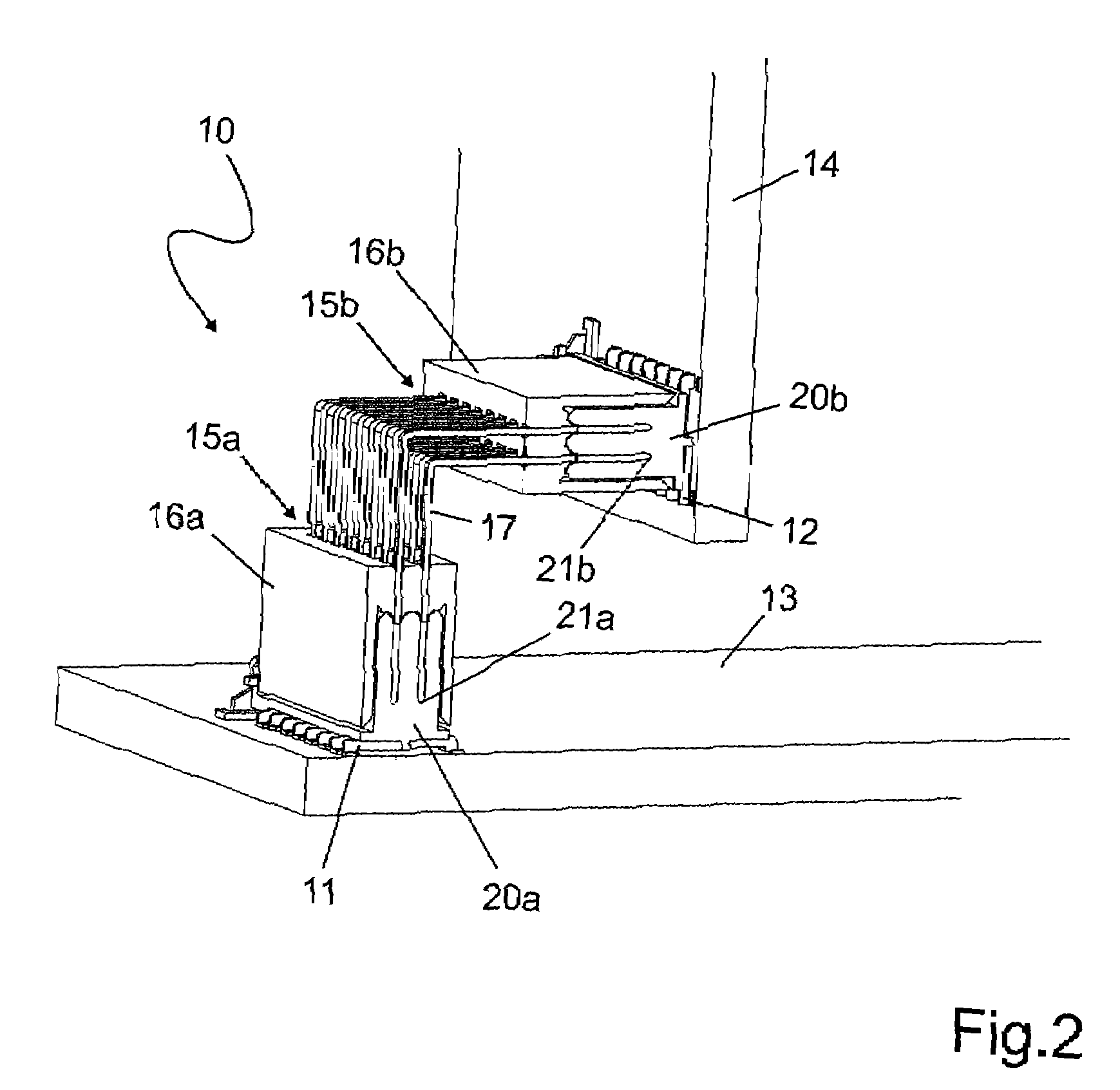
[0030]FIG. 1 shows a perspective view of a plug connection adapter 10 suited for connecting a first with a second plug-in connector element 11, 12. The first plug-in connector element 11 is associated to a first component 13, the second plug-in connector element 12 to a second component 14. At least one of the components 13, 14 may be a card. In the illustrated embodiment, the two components 13, 14 are arranged at an angle of 90 degrees, for example, one relative to the other.

[0031]The plug connection adapter 10 carries on at least one of its ends 15a, 15b a header shroud 16a, 16b that encloses a plurality of contact pins 17. In principle, the plug connection adapter 10 may comprise only a single contact pin 17. In the illustrated embodiment, the plug connection adapter 10 is shown to be fitted on both the first plug-in connector element 11 and the second plug-in connector element 12. Correspondingly, the plug connection adapter 10 comprises a first header shroud 16a on its one end ...


PUM


Abstract

In a plug connection adapter adapted for connecting a first and a second plug-in connector element (11, 12) and comprising at least one contact pin (17) both ends of which are provided with contact blades/contact slots (21a, 21b) for contact-making of the plug-in connector elements (11, 12), a header shroud (16a, 16b) adapted to guide the plug connection adapter (10) when contacting a plug-in connector element (11, 12) is arranged on at least one end of the plug connection adapter (10).

Description

[0001]The present invention relates to a plug connection adapter according to the preamble of the independent Claim.PRIOR ART[0002]Plug-in connections for printed-wiring boards are offered by Applicant in a variety of different designs. A plug-in connection for printed-wiring boards comprises two plug-in connector elements that can be brought into engagement one with the other. A plug-in connector element generally comprises a plurality of electrically conductive contacts arranged in a plastic housing. A first plug-in connector element is arranged on the printed-wiring board. For connecting the printed-wiring board with other wiring components the second plug-in connector element is plugged onto the first plug-in connector element.[0003]The second plug-in connector element may be connected to another plug-in connector element via a ribbon cable, for example, which can be fitted in a corresponding plug-in connector element arranged on another component.[0004]DE 199 47 031 A describes...

Claims


Application Information

Patent Timeline
IPC IPC(8): H05K1/00
CPCH01R12/7082H01R31/06
Inventor LAPPOEHN, JUERGEN
Owner ERNI PRODION GMBH
Why Eureka
Try Eureka