Piston pump for a high-pressure cleaning appliance

Inactive Publication Date: 2014-11-06
ALFRED KARCHER GMBH & CO KG
View PDF5 Cites 0 Cited by
  • Summary
  • Abstract
  • Description
  • Claims
  • Application Information

AI Technical Summary

Benefits of technology

This patent is about a new piston pump design that simplifies assembly and reduces material usage while maintaining high mechanical stability. The design features a one-piece support shield that includes all of the support rings that support the sealing rings around each piston in the circuit. This support shield is supported by a guide shield that guides the pistons and acts as a cover for the swash plate housing. This configuration increases the mechanical stability of the guide shield and reduces its material thickness. The guide shield also functions to cover the swash plate housing where a swash plate is located, and the pistons interact with the swash plate to change the volumes of the pump chambers.

Problems solved by technology

Furthermore, the relatively high material thickness has the consequence that the housing of the piston pump, which is usually manufactured in a casting process, undergoes a lengthy cooling process during the manufacture, which limits the production rate of the housing.
This also increases the manufacturing costs of the piston pump.

Method used


Image

  • Piston pump for a high-pressure cleaning appliance
  • Piston pump for a high-pressure cleaning appliance
  • Piston pump for a high-pressure cleaning appliance

Examples


Embodiment Construction

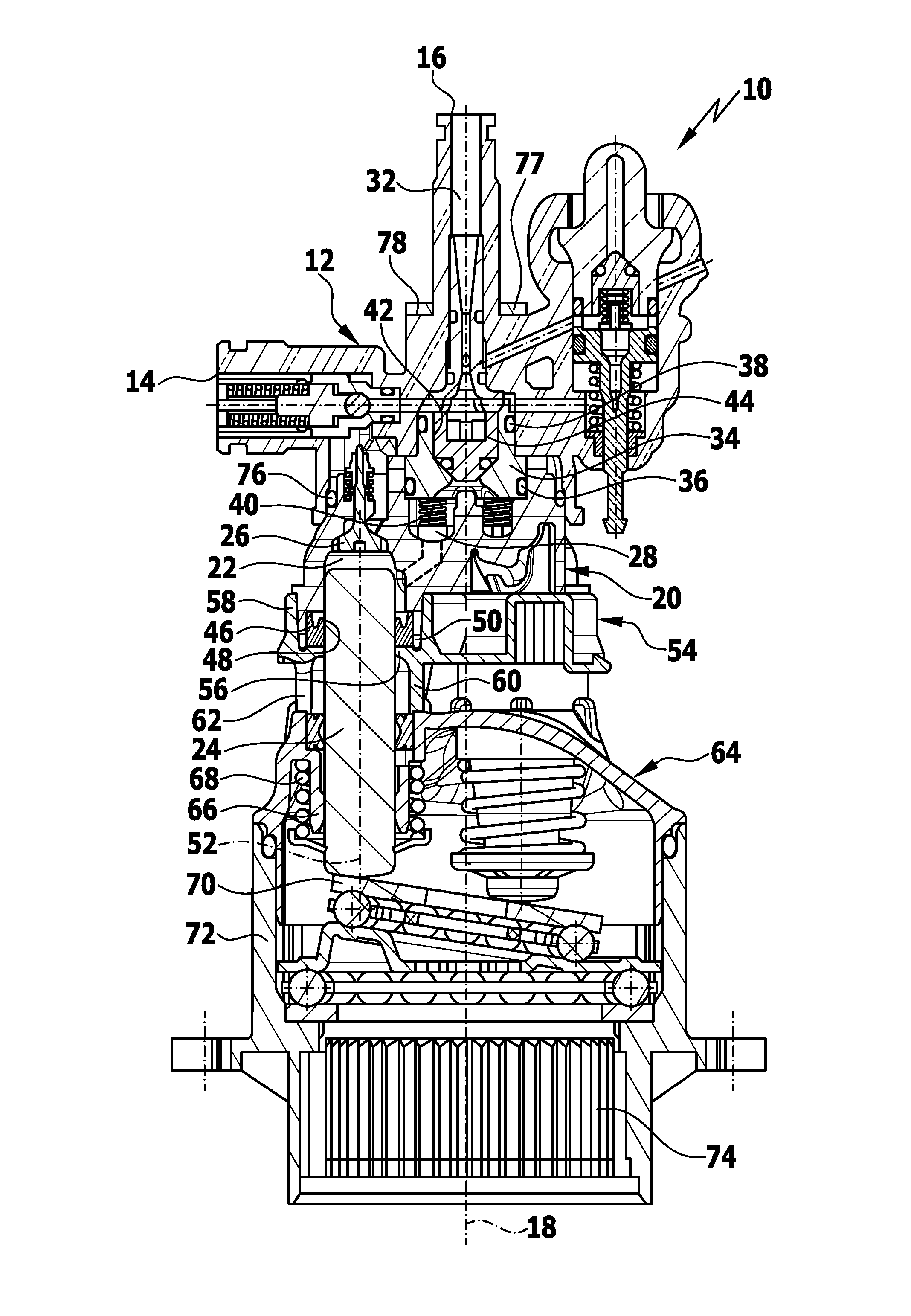
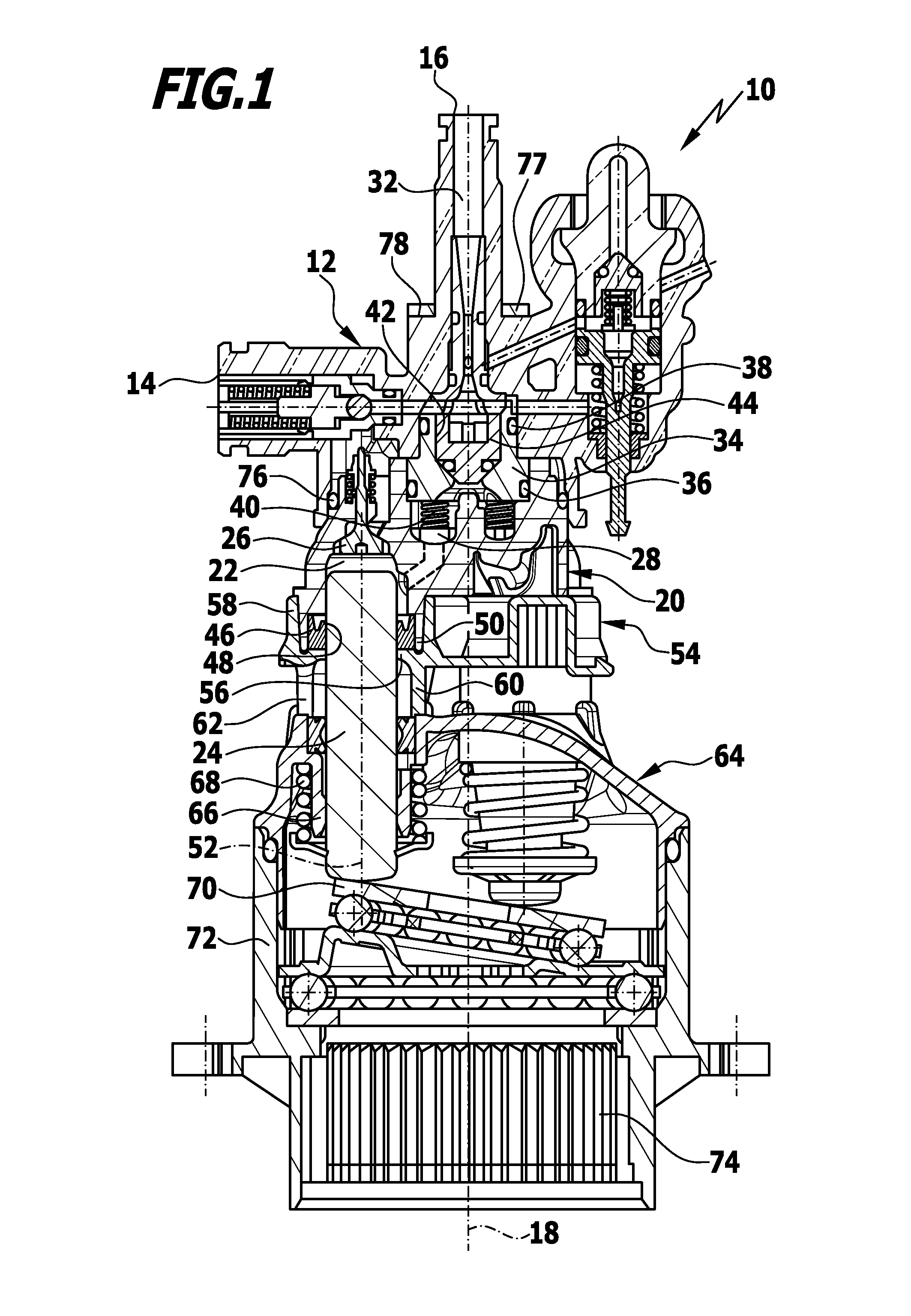
[0027]An advantageous embodiment of a piston pump in accordance with the invention, generally denoted by reference numeral 10, is shown schematically in the drawings. The piston pump 10 comprises a pump head 12 with a suction inlet 14, via which a liquid to be pressurized, preferably water, can be supplied to the piston pump 10. A supply line, for example, can be connected to the suction inlet 14. The pump head 12 also comprises a pressure outlet 16 via which the pressurized liquid can be discharged. A pressure hose, for example, carrying at its free end a discharge member for the pressurized liquid, for example, a spray lance or a spray nozzle can be connected to the pressure outlet 16.

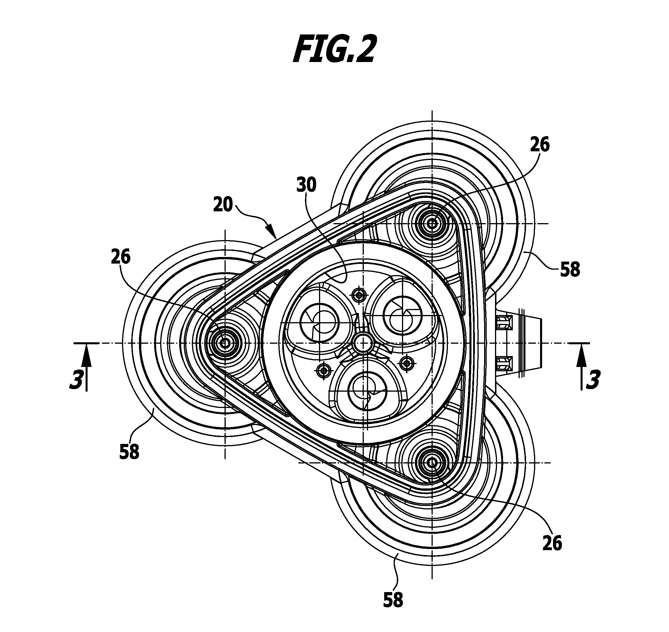
[0028]The pump head 12 is fitted in the axial direction, in relation to a longitudinal pump axis 18, on a pump block 20 comprising a plurality of pump chambers 22, into each of which one piston 24 plunges. The piston pump 10 shown in the drawings has a total of three pump chambers. Only one pump cham...


PUM


Abstract

A piston pump for a high-pressure cleaning appliance is provided, including a plurality of pump chambers into each of which one piston which is movable back and forth plunges, and which are each in flow connection via a suction valve with a suction inlet and via a pressure valve with a pressure outlet, the pistons each being surrounded by a sealing ring which is supported in the radial direction by a ring wall and in the axial direction by a support ring. In order to develop the piston pump in such a way that it can be manufactured and assembled more cost-effectively, it is proposed that the piston pump includes a one-piece support shield which forms the support rings and surrounds the ring walls in the circumferential direction.

Description

CROSS-REFERENCE TO RELATED APPLICATIONS[0001]This application is a continuation of international application number PCT / EP2012 / 050867, filed on Jan. 20, 2012, which is incorporated herein by reference in its entirety and for all purposes.BACKGROUND OF THE INVENTION[0002]The invention relates to a piston pump for a high-pressure cleaning appliance, comprising a plurality of pump chambers into each of which one piston which is movable back and forth plunges, and which are each in flow connection via a suction valve with a suction inlet and via a pressure valve with a pressure outlet, the pistons each being surrounded by a sealing ring which is supported in the radial direction by a ring wall and in the axial direction by a support ring.[0003]A liquid, preferably water, can be pressurized and directed at an article to be cleaned or a surface to be cleaned by means of such piston pumps. For this purpose, the pistons can be reciprocatingly driven, for example, by means of a swash plate, ...

Claims


Application Information

Patent Timeline
IPC IPC(8): F04B1/20
CPCF04B1/2078F04B53/02F04B53/164F04B1/143
Inventor NATHAN, ROBERT
Owner ALFRED KARCHER GMBH & CO KG
Why Eureka
Try Eureka