Demolition tool

a demolition tool and multi-functional technology, applied in the field of multi-functional demolition tools, can solve the problems of presenting certain drawbacks or limitations of demolition tools, and limiting the range of motion of certain tools with the end of the pry bar,

Active Publication Date: 2007-10-04
STANLEY WORKS THE +1
View PDF73 Cites 32 Cited by
  • Summary
  • Abstract
  • Description
  • Claims
  • Application Information

AI Technical Summary

Benefits of technology

[0010] In one embodiment, the demolition tool includes a bent end pry bar at a second end of the handle. Bent end pry bar may enable the removal of fasteners such as, for example, nails, brads, staples, or other fasteners, or may enable general prying apart of materials. In one embodiment, the bent end pry bar is bent in a direction that is 90 degrees offset from the central longitudinal plane of the head. This offset enables the use of the bent end pry bar without interference from the head or any implements thereon (e.g., the grasping jaws, the strike contact surface, or other implements). Additionally, the 90 degree offset moves the bent end pry bar out of the plane of use of implements on the head.
[0012] The demolition tool, including the handle, the head, the bent end pry bar, and / or other portions of the demolition tool, may comprise a single integrally molded metal material, as opposed to multiple parts jointed or fastened together. In one embodiment, the demolition tool is manufactured to weigh between 3.5 to 4.5 lbs., and in one embodiment, approximately 4 lbs. This weight provides a tool with enough mass and inertia to aid in demolition of construction materials or other materials. In one embodiment, the demolition tool may be hardened to Rockwell C 38-44. Thus, the demolition tool is softer than conventional tools that can be used to strike it, but harder than the materials it is used to strike (e.g., wood, aluminum, or other materials).

Problems solved by technology

However, some of these demolition tools present certain drawbacks or limited capabilities.
For example, typical board grasping equipment is unsuitable for successfully demolishing lumber or grasping materials or boards of different thicknesses.
In addition, certain tools with pry bar ends do not enable full range of motion due to other implements located at opposite ends of the tool bottoming out on a work surface.
Furthermore, the configuration of these pry bar ends often interferes with the comfortable use of the implements located at the other ends of the tool.
This adds to the cost and complexity of the structure, and potentially reduces the strength thereof.

Method used


Image

  • Demolition tool
  • Demolition tool
  • Demolition tool

Examples


Embodiment Construction

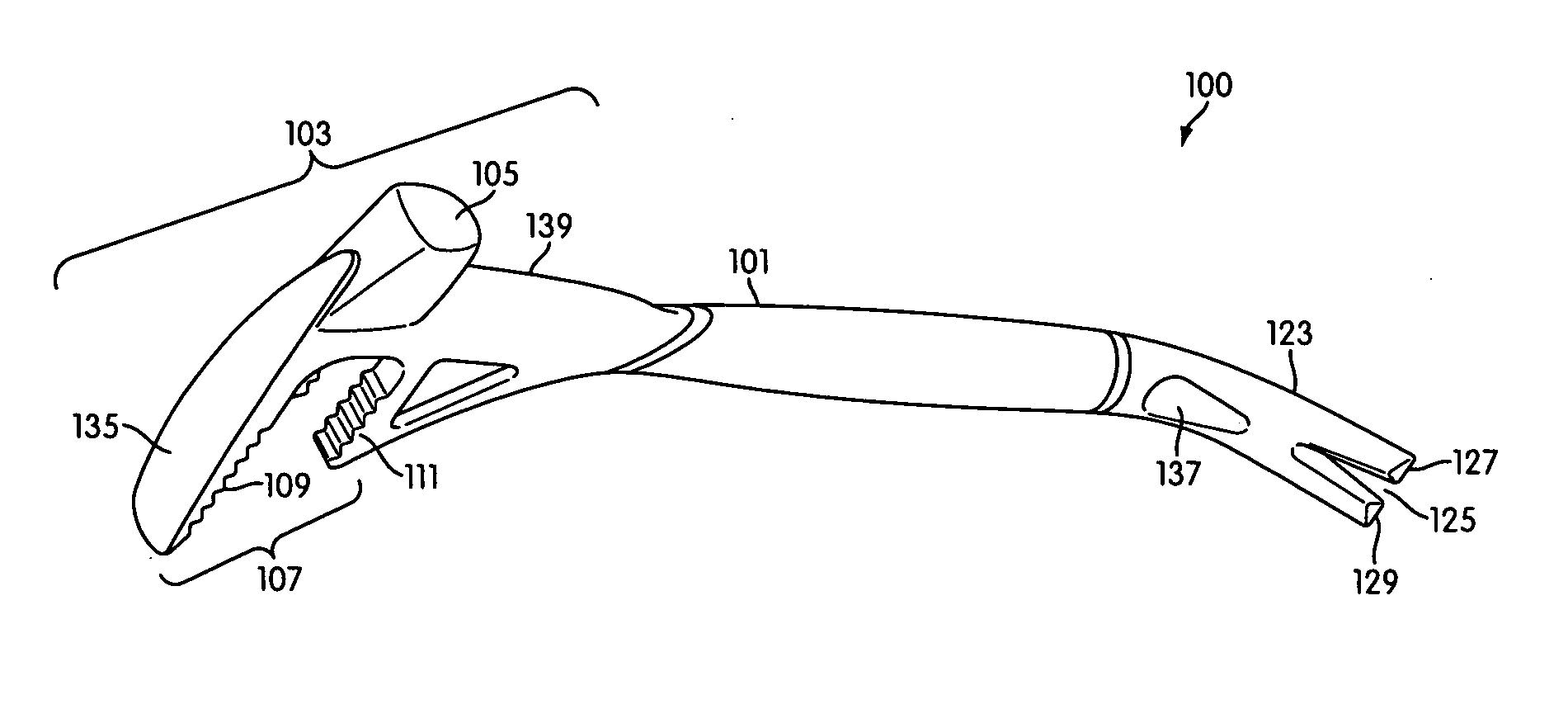
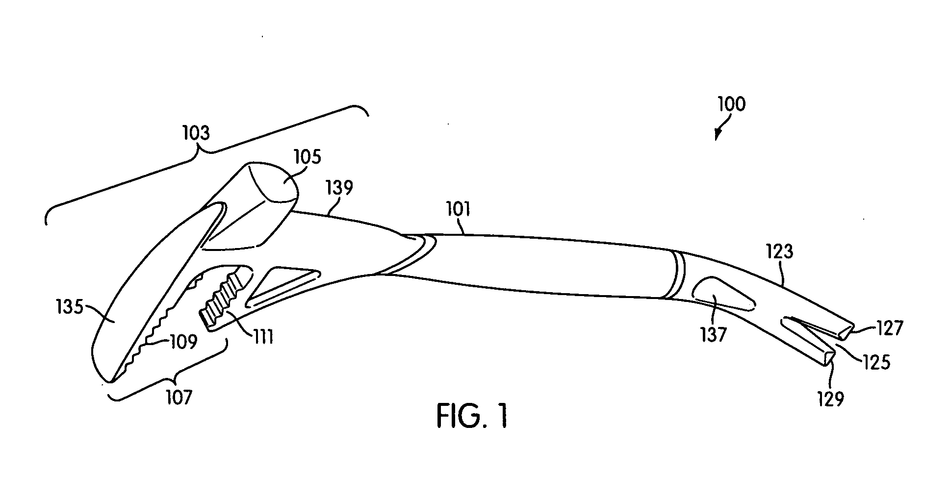
[0021] The invention provides a demolition tool for demolishing construction material, building material, or other material. FIG. 1 illustrates a demolition tool 100 according to an embodiment of the invention. In one embodiment, demolition tool 100 comprises a handle 101 with a head 103 at a first end of handle 101. In one embodiment, head 103 has a longitudinal central plane (plane 131 of FIGS. 4A and 4B) that bisects head 103. In one embodiment, head 103 includes a strike contact face 105. Strike contact face 105 includes a generally flat surface that can be struck by a hammer or other striking tool or that can be used to strike building or other material for demolition purposes or for other purposes. In one embodiment, the plane 106 or surface of strike contact face 105 is parallel with the main axis 121 of handle 101, as illustrated in FIG. 2.

[0022] In one embodiment, head 103 includes grasping jaws 107. In one embodiment, grasping jaws 107 comprise an upper jaw 109 and a lowe...


PUM


Abstract

The invention provides a demolition tool that can be used in many ways for the demolition of construction materials or other materials. The demolition tool includes a handle having a head at one end. The head has a longitudinal central plane that bisects the head, a strike contact face, and toothed, stepped grasping jaws that accommodate multiple sizes of lumber or other material. The head may also include a blunt blade edge below the strike contact face for striking and demolishing material. The demolition tool includes a bent end pry bar at a second end of the handle. The bent end pry bar being offset 90 degrees from the longitudinal central plane of the tool head enabling full range of motion without interfering with other tool functions. The demolition tool may comprise a single piece of material and may be softer than tools used to strike it, but harder than materials which it is used to strike.

Description

BACKGROUND OF THE INVENTION [0001] 1. Field of the Invention [0002] The invention relates to a multi-functional demolition tool and methods for the manufacture thereof. [0003] 2. Description of Related Art [0004] There are many hand tools that are traditionally used for demolition of construction or building materials. A “crow bar,” for instance, typically has a straight pry bar end attached to a long lever arm and a hooked pry bar end at its opposite terminus. Some tools have pry bar ends that are forked for use in removing nails or other fasteners and otherwise wedging into building materials. Additional demolition tools include various sledge hammers, grasping equipment, and other tools. [0005] However, some of these demolition tools present certain drawbacks or limited capabilities. For example, typical board grasping equipment is unsuitable for successfully demolishing lumber or grasping materials or boards of different thicknesses. In addition, certain tools with pry bar ends ...

Claims


Application Information

Patent Timeline
Patent Type & Authority Applications(United States)
IPC IPC(8): B25D1/00B25D1/04
CPCB25F1/00E04G23/08B66F15/00E04G23/082E04G2023/085B25F1/006
Inventor WOOLLEY, CHRISTOPHERMARUSIAK, MICHAELMARTONE, JOSEPHRANIERI, ERICPOWERS, RUSSELL
Owner STANLEY WORKS THE
Why Eureka
Try Eureka