
Eureka
For R&D, Eureka makes reading and utilizing patents & technical documents easy.
Eureka AIR
Designed for self-driven R&D workflows. Generate viable solutions, solve complex R&D challenges, empower your innovation with AI.

Eureka Materials
Designed for material experts only. Revolutionize your material R&D, from search, analyze, to developing new materials.

TechResearch
Generate reliable direction feasibility study reports for your R&D in just a few steps.

TechSeek
Discover and master advanced knowledge NOW. Basics, ideas, possibilities, all at once.

TechMind
As an expert in R&D Theories, TechMind can generates customized viable solutions instantly.

TechRisk
Analyze your overall solution with one click, know your potential R&D risks in advance.

TechMonitor
Get weekly tech updates, stay abreast of the latest tech innovations and key insights.
Tool Incorporating a Light Line Generating Device
- Summary
- Abstract
- Description
- Claims
- Application Information
AI Technical Summary
Problems solved by technology
Method used
Image

Examples
Embodiment Construction
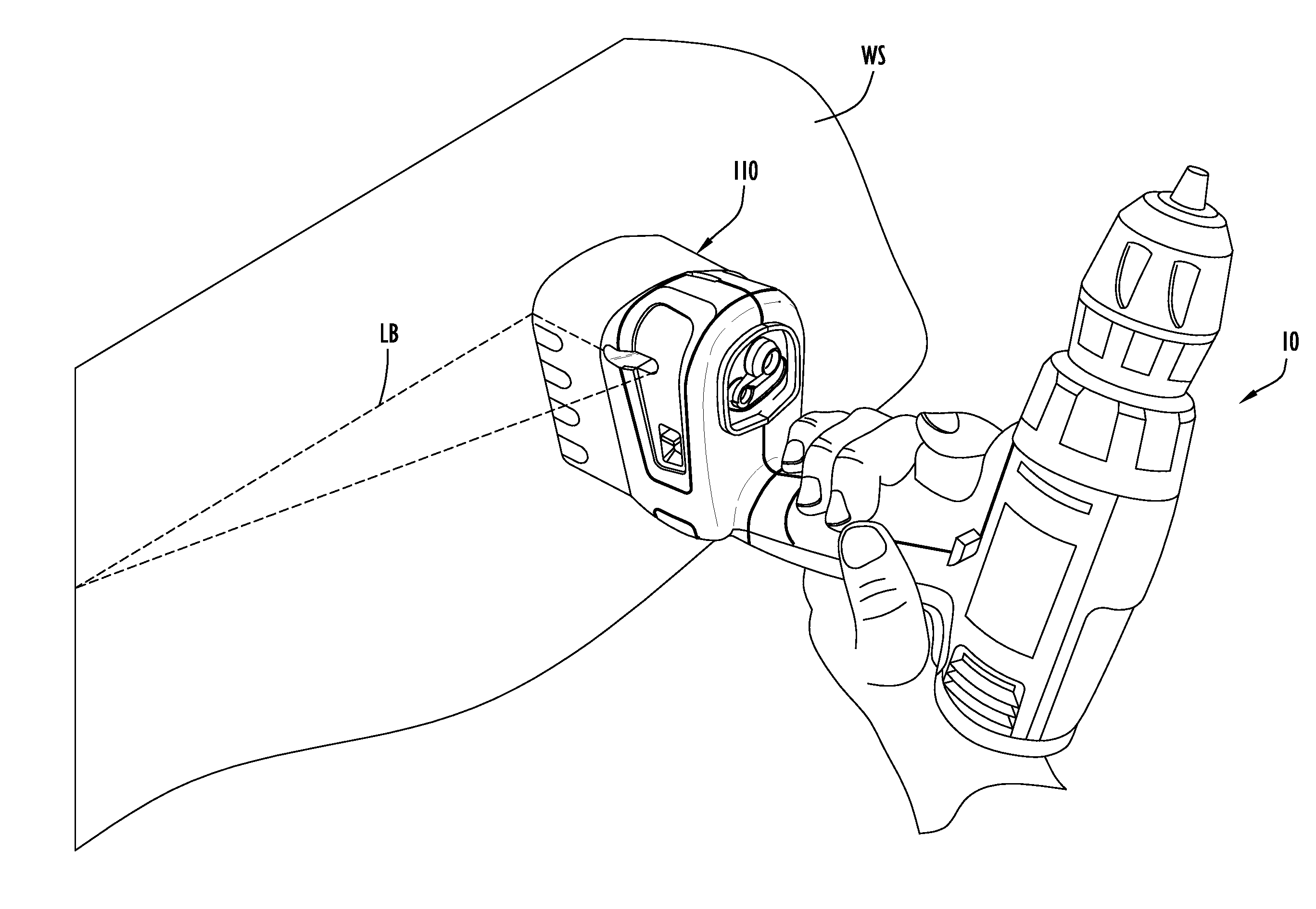
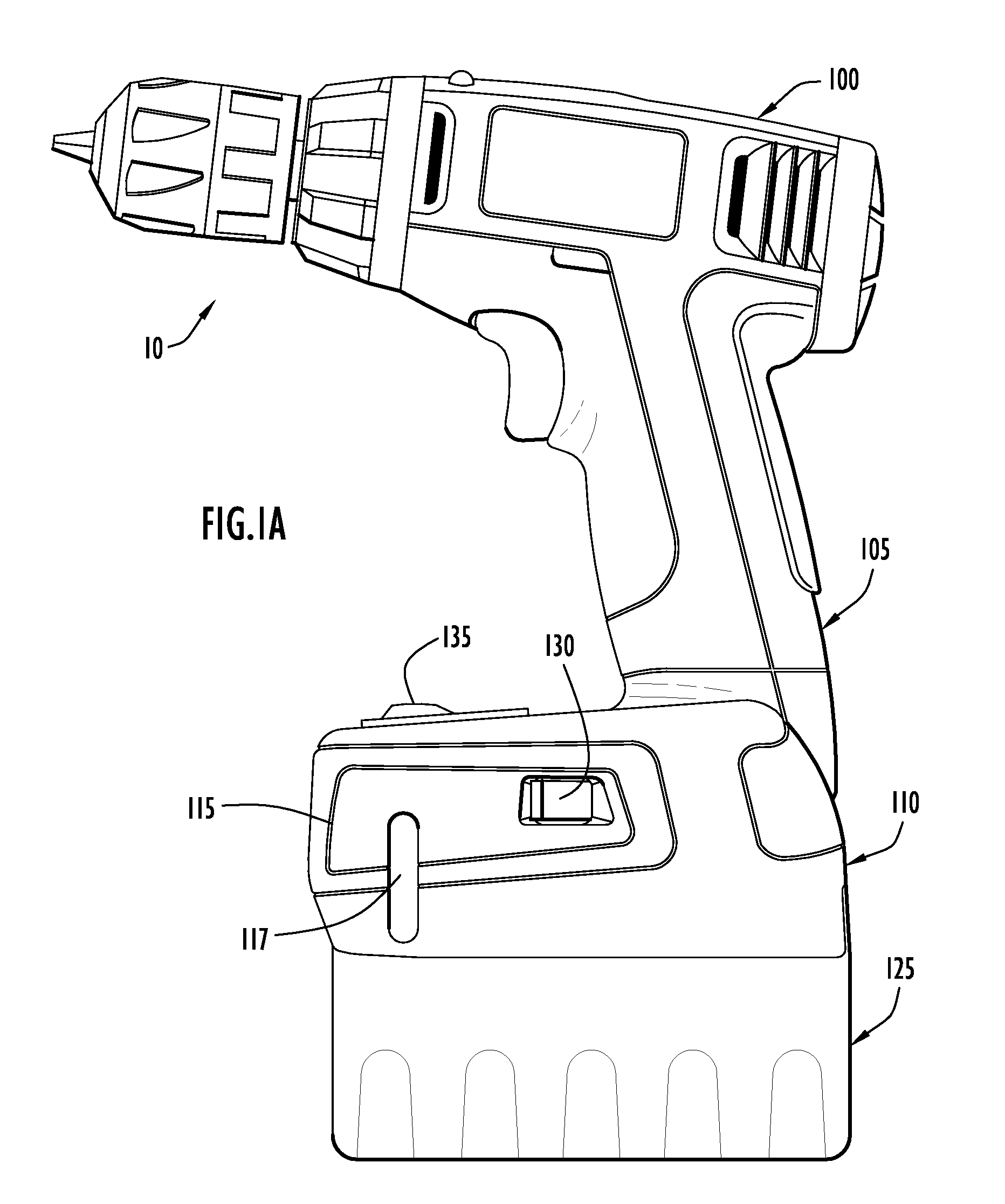
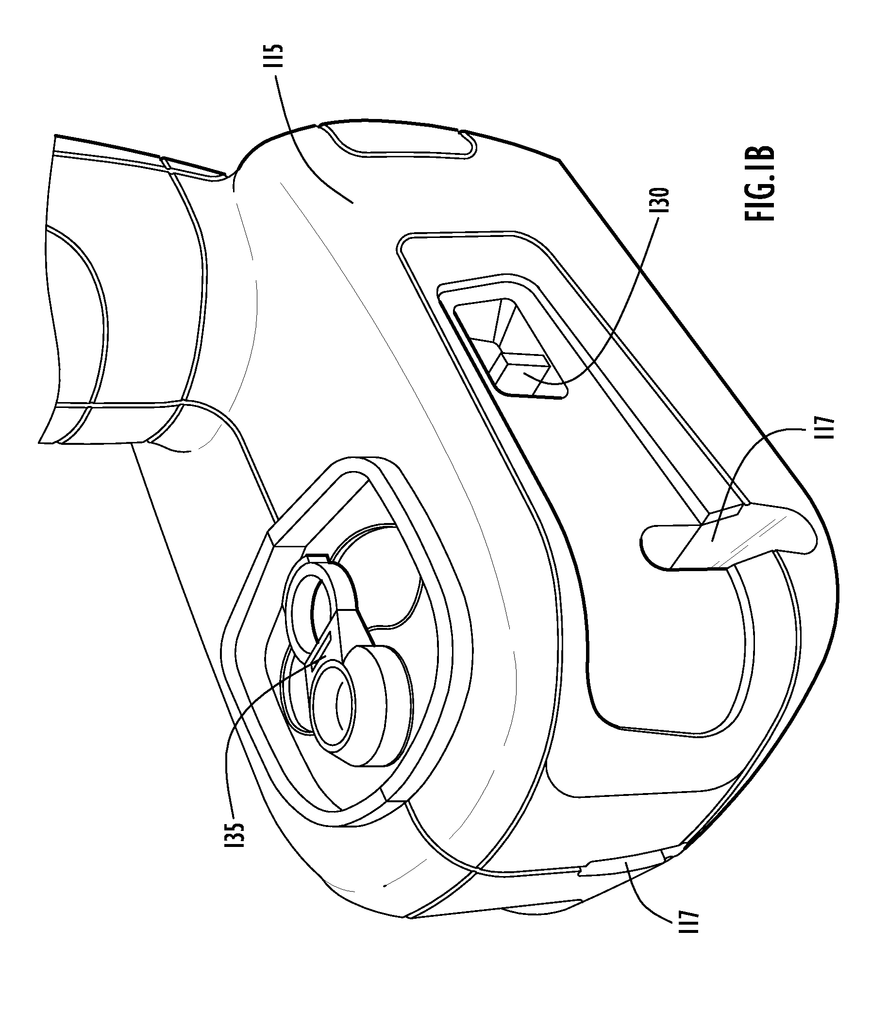
[0012]FIG. 1A is side view in of a tool 10 incorporating a light generating device according to an embodiment of the present invention. As illustrated, the tool 10 may include a tool portion 100 (e.g., a drill), a handle portion 105 and a support base 110. The tool portion 100 may include a tool element that acts on a work surface such as a wall. By way of example, the tool element may be a drill bit or other drill attachment. The tool 10 may be formed from a hard, impact-resistant, preferably moldable material such as a hard thermoplastic material (e.g., ABS or polystyrene). The tool 10 may also include a grip portion formed from soft or low durometer thermoplastic elastomer. Alternatively or additionally, the grip portion may be formed from “soft-touch” elastomer materials such as SANTOPRENE, KRATON, and MONOPRENE. In addition, the base 110 may include a power source 125 operable to connect thereto (e.g., when the tool 10 is cordless device a battery power source may be utilized)....
PUM
 Abstract
Description
Claims
Application Information
 - R&D Engineer
- R&D Manager
- IP Professional
- Industry Leading Data Capabilities
- Powerful AI technology
- Patent DNA Extraction
Browse by: Latest US Patents, China's latest patents, Technical Efficacy Thesaurus, Application Domain, Technology Topic, Popular Technical Reports.
© 2024 PatSnap. All rights reserved.Legal|Privacy policy|Modern Slavery Act Transparency Statement|Sitemap|About US| Contact US: help@patsnap.com