
Method and apparatus for locating and decoding a two-dimensional machine-readable symbol

a machine-readable symbol and two-dimensional technology, applied in the field of symbol recognition, can solve the problems of inability to encode a limited amount of information, inability to decode two-dimensional symbols that require relatively large amounts of computation, and inability to accurately map a reference grid, etc., to achieve simple and computationally straight-forward mapping and accurate mapping

Inactive Publication Date: 2007-10-04
SEIKO EPSON CORP
View PDF12 Cites 57 Cited by
  • Summary
  • Abstract
  • Description
  • Claims
  • Application Information

AI Technical Summary

Benefits of technology

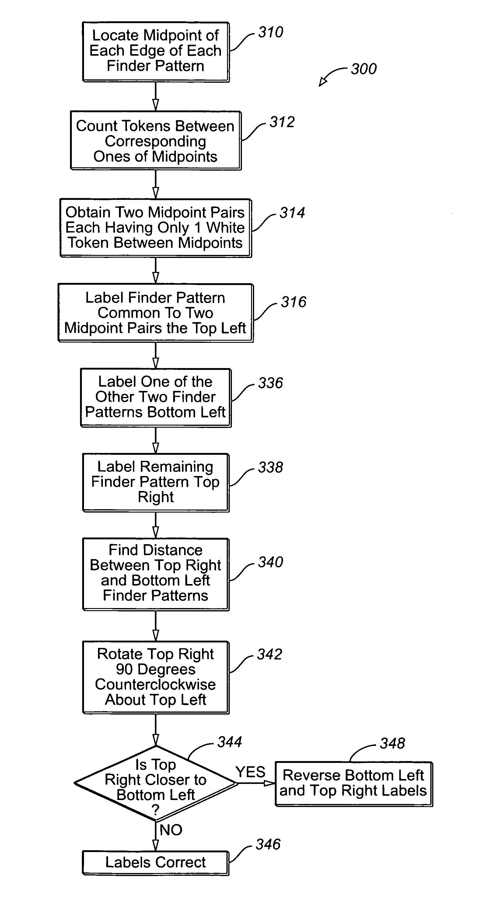
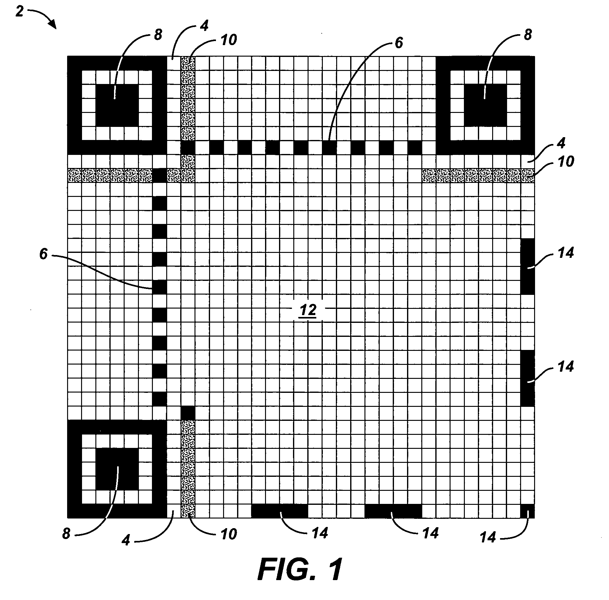
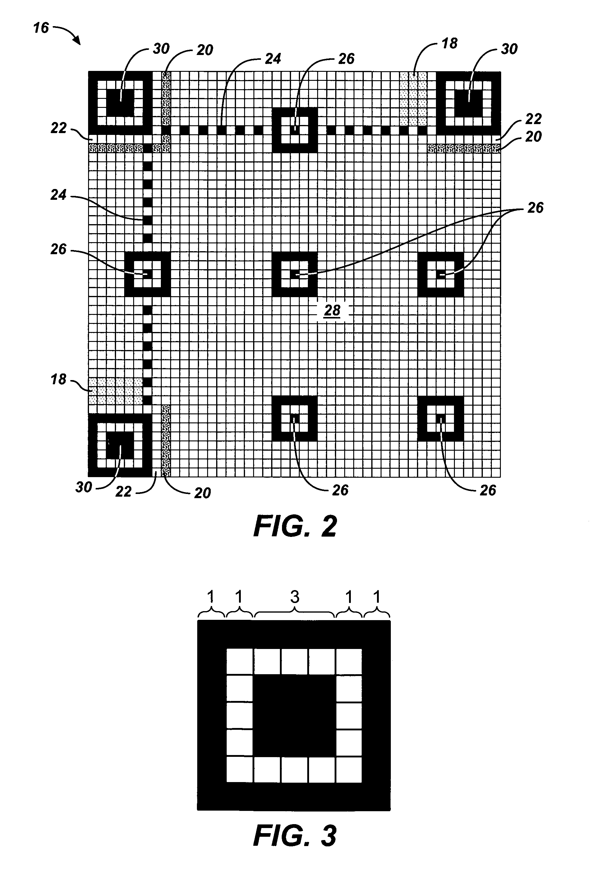
The patent describes a method and apparatus for extracting a bitstream from a machine-readable symbol in an image. The symbol comprises three finder patterns that are positioned at the corners of a right-angled triangle. The method involves identifying the finder patterns, orienting the symbol using the finder patterns, and delineating the corners of the triangle based on the relative distance between the finder patterns. The apparatus includes a finder pattern identifier and a symbol orientor. The technical effect of the patent is to provide a reliable and efficient method for extracting bitstreams from machine-readable symbols in images.

Problems solved by technology

Although these one-dimensional barcode symbols are easily scanned and decoded, they suffer disadvantages in that they are only capable of encoding a limited amount of information.
In fact decoding two-dimensional symbols often requires relatively large amounts of computation.
Although the above references disclose methods of locating and extracting data from QR-Code symbols in a digital image, symbol orientation is either taken for granted or computationally expensive.
Furthermore, these disclosed methods do not address situations in which the symbol is either skewed or pitched in the digital image.

Method used


Image

  • Method and apparatus for locating and decoding a two-dimensional machine-readable symbol
  • Method and apparatus for locating and decoding a two-dimensional machine-readable symbol
  • Method and apparatus for locating and decoding a two-dimensional machine-readable symbol

Examples


example

[0195] Version: 7 [0196] Binary string: 000111 [0197] Polynomial: x2+x+1 [0198] Raise power to the (18-6)th: x14+x13+x12 [0199] Divide by G(x): =(x12+x11+x10+x9+x8+x5+x2+1)x2+(x11+x10+x7+x4+x2)

[0200] Add Coefficient String of Above Remainder Polynomial to Version Information Data String: [0201] 000111+110010010100 000111110010010100

[0202] The version number is obtained by checking for errors in the version information at the bottom left of the QR-Code symbol. If there is no error, then the version number is represented by the six (6) most significant bits of the bottom left version information bits. If there is an error, then the version information at the top right of the QR-Code symbol is checked for errors. If there is no error, then the version number is represented by the six (6) most significant bits of the top right version information bits.

[0203] Because of the nature of QR-Code, a mathematical formula cannot be employed to locate and correct errors in the version informa...


PUM


Abstract

A method of locating and decoding a two-dimensional machine-readable symbol in a digital image, where the symbol has three finder patterns adjacent respective corners of the symbol, takes into account the possibility of skew and pitch when delineating the symbol in the digital image by estimating the unknown fourth corner based on lines passing through known symbol edge points. On the basis of the delineating, a reference grid is mapped to the digital image and a bit stream is extracted based on the mapping.

Description

FIELD OF THE INVENTION [0001] The methods and systems disclosed herein relate generally to symbol recognition and more specifically, to a method, apparatus and computer program for locating and decoding a two-dimensional machine-readable symbol in a digital image. BACKGROUND OF THE INVENTION [0002] Marking documents with machine-readable characters to facilitate automatic document recognition using character recognition systems is well known in the art. In many industries, labels are printed with machine-readable symbols, often referred to as barcodes, and are applied to packages and parcels. The machine-readable symbols on the labels typically carry information concerning the packages and parcels that is not otherwise evident from the packages and parcels themselves. [0003] For example, one-dimensional barcode symbols, such as those following the well-known Universal Product Code (UPC) specification, regulated by the Uniform Code Council, are commonly used on machine-readable label...

Claims


Application Information

Patent Timeline
Patent Type & Authority Applications(United States)
IPC IPC(8): G06K7/10G06V30/224
CPCG06K7/1417G06K7/14
Inventor THIYAGARAJAH, MOHANARAJ
Owner SEIKO EPSON CORP
Learn More