Camera Module, and Portable Terminal and Information Terminal with the Same

a technology of portable terminals and information terminals, applied in the direction of cameras, printers, instruments, etc., can solve the problems of increasing frictional force, hammering the miniaturization of the camera module, noise and the like, etc., to prevent ghosting and flare, prevent lens polluting, and prevent the effect of exerting influen

Inactive Publication Date: 2007-10-04
KYOCERA CORP
View PDF3 Cites 38 Cited by
  • Summary
  • Abstract
  • Description
  • Claims
  • Application Information

AI Technical Summary

Benefits of technology

[0056] According to the first aspect, even when the operating portion of the piezo element abuts on the shaft member to generate shavings the shavings are collected by the dust collecting member disposed in the vicinity of the shaft hole portion. Therefore, it is possible to prevent lenses from being polluted by the shavings as powder dust and to prevent ghost and flare from being caused. Moreover, the camera module having an auto-focusing (AF) function and a zooming function can be constituted to be small and light.
[0057] According to the second aspect, the dust collecting member is disposed on the side on which the operating portion of the piezo element in the shaft hole portion abuts on the shaft member. That is, the dust collecting member is disposed in the vicinity of a place where the shavings are generated, and the shavings can be collected before they fly and scatter.
[0058] According to the third aspect, the shaft hole portion is provided with the dust collecting member disposed on one side thereof, and a sliding portion disposed on the side opposite to the dust collecting member via the shaft member, and the shaft hole portion is formed so as to surround the shaft member. By this constitution, the shavings do not fly or scatter from this shaft hole portion, are collected by the dust collecting member and are prevented from exerting influe

Problems solved by technology

However, the electromagnetic motor using such a rotor also requires an electromagnet and a permanent magnet around the rotor.
This hampers the miniaturization of the camera module.
Furthermore, noises and the like are generated.
However, in such a frictional driving type driving source using the piezo element (PZT) or the like, a portion where th

Method used


Image

  • Camera Module, and Portable Terminal and Information Terminal with the Same
  • Camera Module, and Portable Terminal and Information Terminal with the Same
  • Camera Module, and Portable Terminal and Information Terminal with the Same

Examples


embodiment 1

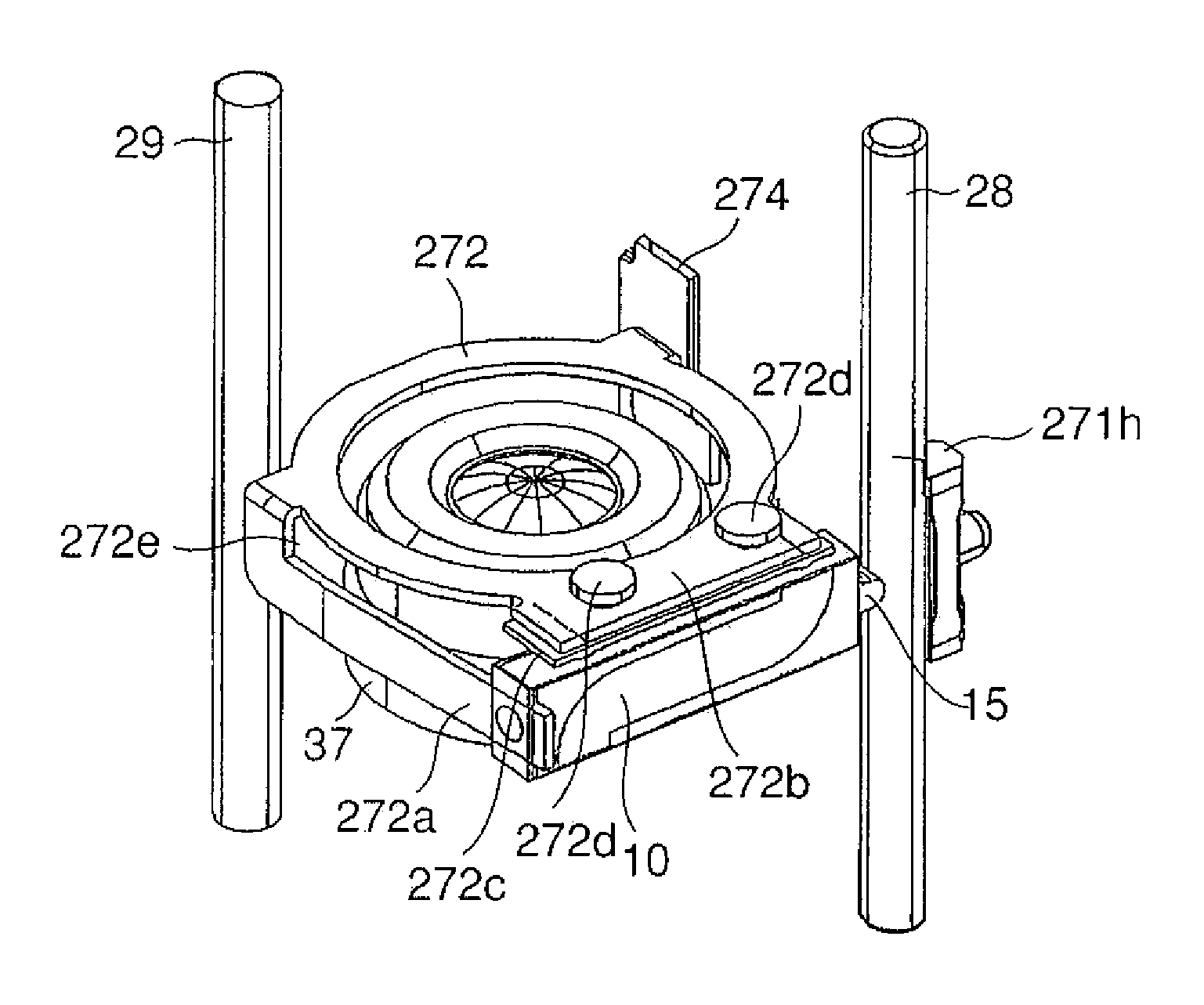
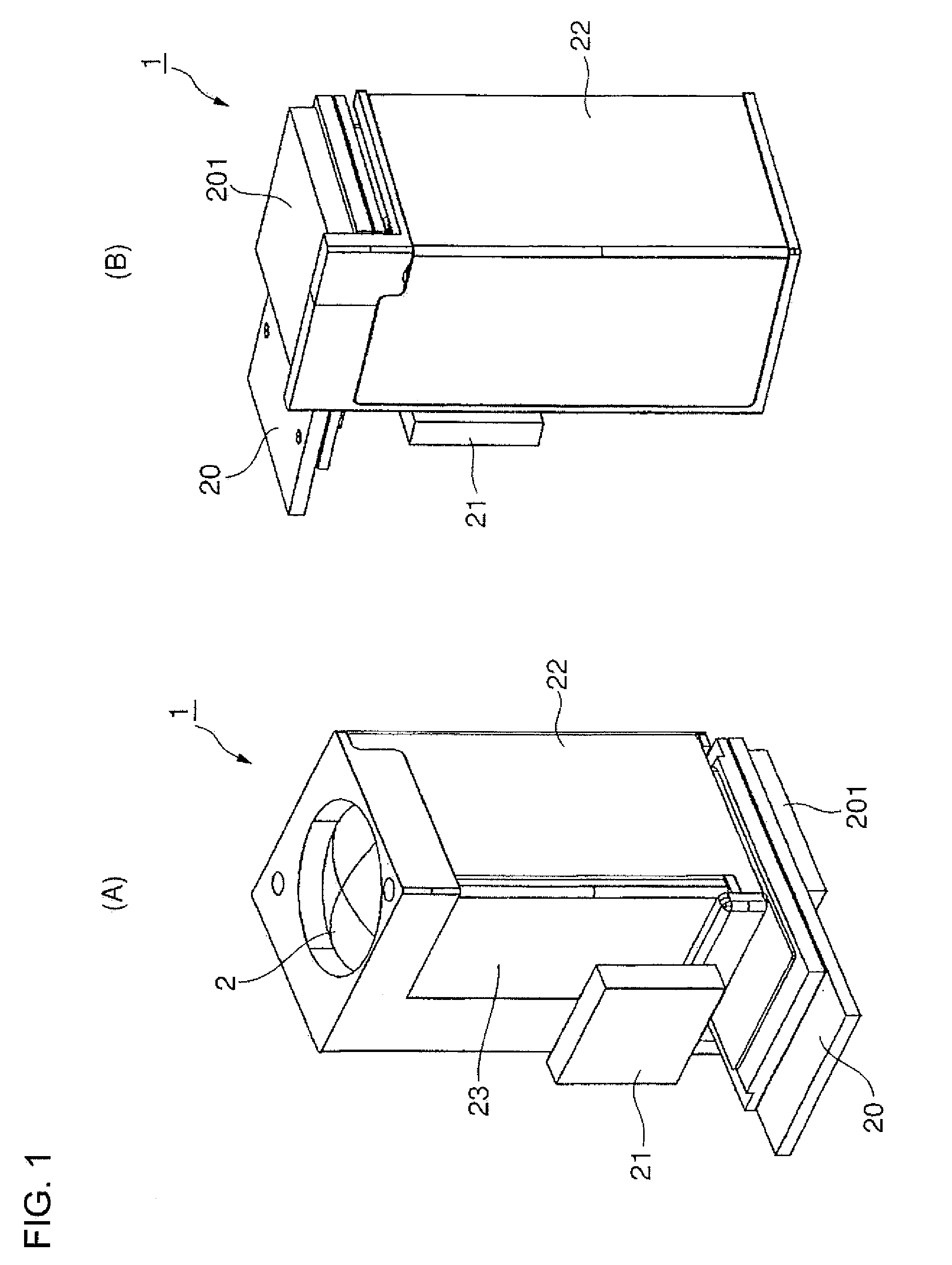
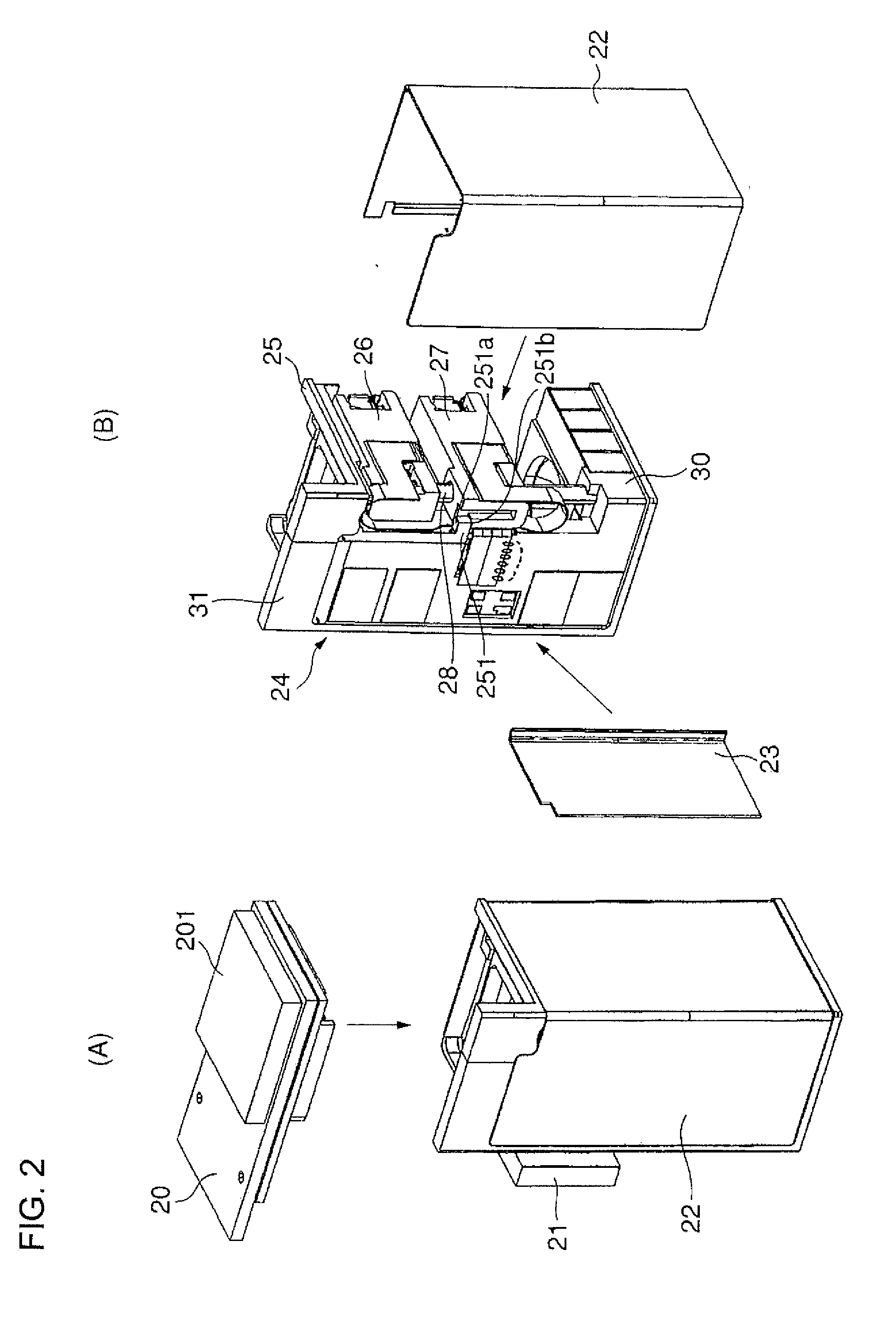
[0149] Embodiment 1 will be described with reference to FIGS. 1 to 14 and 21. FIG. 1(A) is an appearance perspective view of a camera module of Embodiment 1 viewed from a subject side lens direction, and (B) is an appearance perspective view viewed from an image pickup element side; FIG. 2(A) is a perspective view from which an image pickup element module is removed, and (B) is a perspective view from which a side cover is further removed in the camera module of the embodiment of FIG. 1(B) viewed from the image pickup element side; FIG. 3 is an exploded diagram showing a constitution of the image pickup element module; FIG. 4(A) is a perspective view from which an image pickup element side lower cover is removed, (B) is a perspective view from which a first lens holding frame holding a third lens unit is removed, and (C) is a perspective view from which a second lens holding frame holding a second lens unit is removed in the camera module of Embodiment 1; FIG. 5 is a perspective vie...

embodiment 2

[0191]FIG. 15 is a schematic sectional view of a camera module showing a driving portion according to Embodiment 2; FIG. 16 shows a perspective view (A) of the camera module of FIG. 15 as viewed from a subject side lens and a perspective view (B) viewed from an image pickup elemental side; FIG. 17 is an operation explanatory view of the camera module according to the present embodiment, shows a state (a) in which the lenses are arranged at a telephoto position (tele), and similarly shows a state (b) in which the lenses are arranged at a wide-angle position (wide); FIG. 18 shows diagrams of an abutment state between a sliding member and a driving shaft, and shows a side sectional view (a), a flat sectional view (b) and a main part sectional view (c); FIG. 19 is a structure explanatory view of the camera module according to the present embodiment, and shows a left side view (a), a top plan view (b), a right side view (c), a perspective view (d) viewed from below on the left, a perspec...


PUM


Abstract

A camera module and a portable terminal comprising the camera module, in which an auto-focus (AF) function and a zoom function are assembled by using a friction drive-type drive source such as a piezoelectric element, which are constructed to be small in size and light in weight, and which are resistant to chips produced through friction contact between the piezoelectric element and driven member. The camera module has a lens holding section for holding at least one or more optical lenses and provided with a shaft hole portion, a shaft member inserted in the shaft hole portion and installed substantially in parallel with the optical axis, a piezoelectric element having at an end an operation portion that is in contact with the shaft member and is placed in the vicinity of the shaft hole portion of the lens holding section, and an adhesive member provided in the vicinity of the shaft hole portion. As a result, the camera module is small in size and light in weight, and chips produced through frictional contact between the piezoelectric element and the driven member are prevented from scattering by the adhesive member.

Description

TECHNICAL FIELD [0001] The present invention relates to a camera constituted to be small and light, and a portable terminal and an information terminal including this camera module. BACKGROUND ART [0002] In recent years, with high pixilation of an image pickup device (a CCD), a camera module for use in a portable terminal such as a cellular phone is required to have functions such as a high-speed high-precision auto-focus (AF) function and a focal length change (zoom) function which are similar to those of a usual electronic camera (a digital camera). Furthermore, with miniaturization and lightening of the portable terminal itself, it is necessarily demanded that the camera module should be miniaturized and lightened. [0003] In order to perform auto-focusing and changing of a focal length (zooming) in such a camera module, a lens unit needs to be moved in an optical axis direction. To achieve this, in a conventional technology, as described in, for example, Patent Document 1, a mech...

Claims


Application Information

Patent Timeline
IPC IPC(8): H04N5/225
CPCG02B7/102H04N5/2254G02B13/009H04N23/52H04N23/55G03B5/00G03B3/10G03B13/36G03B2205/0007G03B2205/0069
Inventor SHIRONO, MASAHIROKOBAYASHI, HIROKAZUKITAMURA, NOBUOARAIE, KEIJI
Owner KYOCERA CORP
Why Eureka
Try Eureka