Lens barrel having shutter flexible circuit board and image pickup apparatus having the same

a flexible circuit board and lens barrel technology, applied in the direction of instruments, printers, cameras focusing arrangements, etc., can solve the problems of low workability in assemblage and wire disconnection, and achieve the effect of improving workability in assembling

Inactive Publication Date: 2014-05-27
CANON KK
View PDF11 Cites 0 Cited by
  • Summary
  • Abstract
  • Description
  • Claims
  • Application Information

AI Technical Summary

Benefits of technology

[0007]The present invention provides a lens barrel capable of improving the workability in assembling a shutter flexible circuit board and capable of preventing a force that acts to press the shutter flexible circuit board into inside the lens barrel from being applied to the shutter flexible circuit board at the time of assemblage.
[0009]With this invention, it is possible to improve the workability in assembling the shutter flexible circuit board and to prevent a force acting to press the shutter flexible circuit board into inside the lens barrel from being applied to the shutter flexible circuit board at the time of assemblage. It is therefore possible to prevent ghost or flare from being caused by photographing light being reflected by the shutter flexible circuit board and to prevent wire disconnection from being caused by the shutter flexible circuit board being pinched between component parts of the lens barrel when the lens barrel is brought into a retracted state.

Problems solved by technology

Accordingly, the lens barrel must be moved forward in order to insert the connection member into the through hole of the fixed barrel, resulting in low workability in assemblage.
In that case, there is a fear that ghost or flare is caused by reflection of light passing through a photographing optical system by the shutter flexible circuit board pressed into inside the lens barrel, or that wire disconnection is caused by the shutter flexible circuit board being pinched between component parts inside the lens barrel when the lens barrel is brought into a retracted state.

Method used


Image

  • Lens barrel having shutter flexible circuit board and image pickup apparatus having the same
  • Lens barrel having shutter flexible circuit board and image pickup apparatus having the same
  • Lens barrel having shutter flexible circuit board and image pickup apparatus having the same

Examples


Embodiment Construction

[0026]The present invention will now be described in detail below with reference to the drawings showing a preferred embodiment thereof.

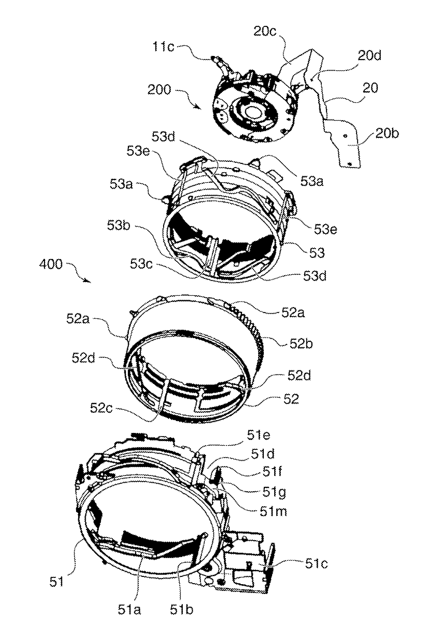
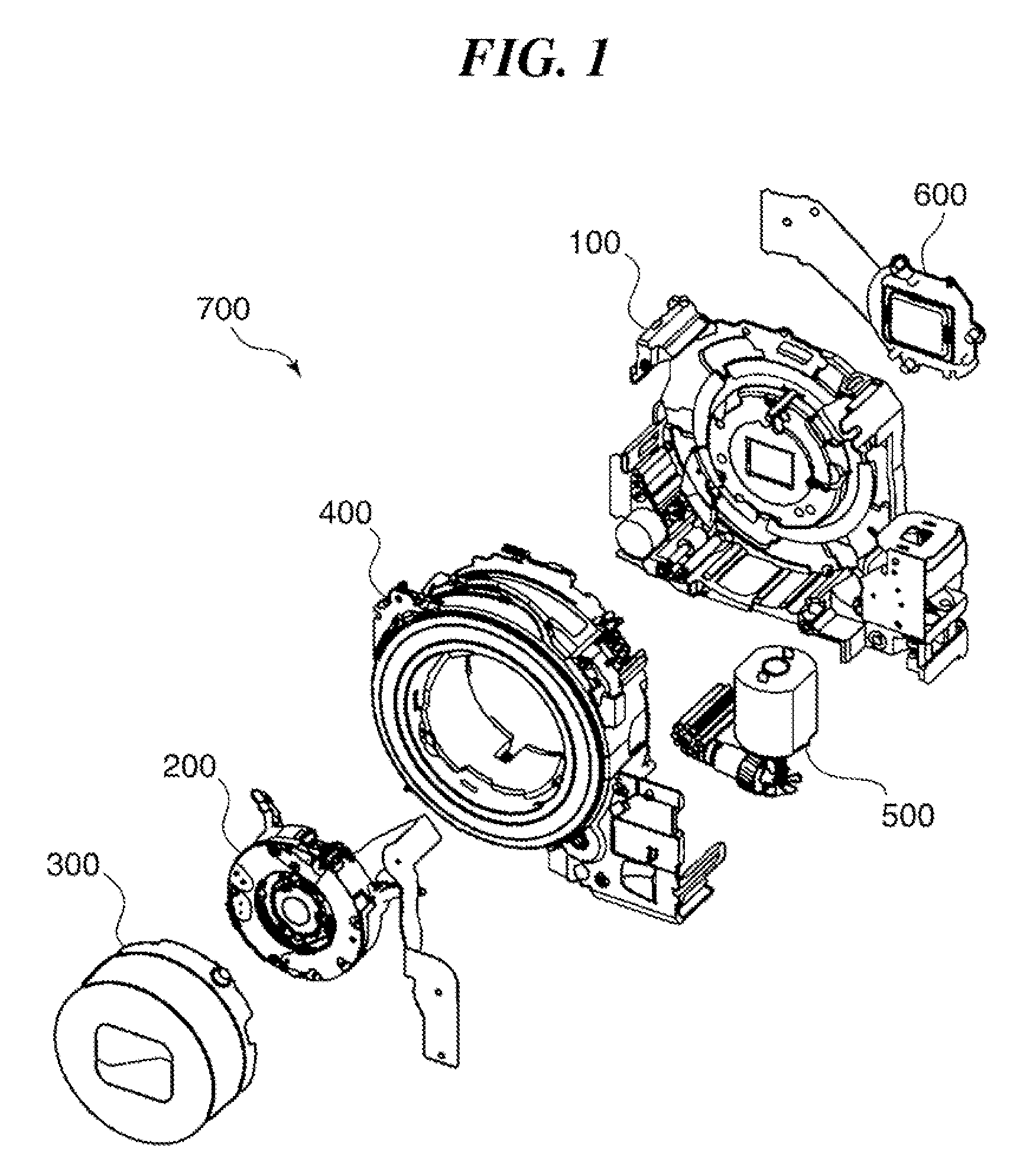
[0027]FIG. 1 shows in exploded perspective view a lens barrel mounted on a digital camera, which is an example of an image pickup apparatus according to one embodiment of this invention.

[0028]As shown in FIG. 1, a lens barrel 700 includes a focus unit 100, second group unit 200, first group unit 300, barrel unit 400, zoom reduction gear unit 500, and imaging device unit 600. The first and second group units 300, 200 (which are an example of first and second lens barrels of this invention) are supported by the barrel unit 400 so as to be movable in an optical axis direction. The barrel unit 400, zoom reduction gear unit 500, and imaging device unit 600 are supported by the focus unit 100.

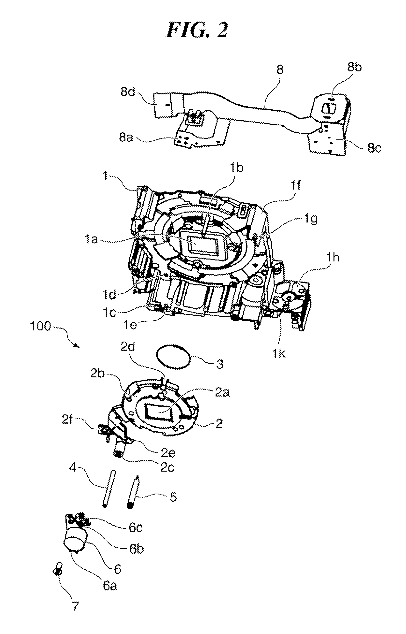
[0029]FIG. 2 shows the focus unit 100 in exploded perspective view.

[0030]As shown in FIG. 2, the focus unit 100 includes a support base plate 1 (which is an example ...


PUM


Abstract

A lens barrel capable of improving the workability in assembling a shutter flexible circuit board and capable of preventing a force that acts to press the shutter flexible circuit board into inside the lens barrel from being applied to the shutter flexible circuit board at the time of assemblage. The lens barrel has a fixed barrel having a notch portion formed thereon through which a coupling portion of the shutter flexible circuit board is inserted and having a fixed shaft formed thereon to project outward in a diametrical direction and to be fitted into a hole of the coupling portion. The lens barrel has a support member formed with a movement preventing portion that prevents the coupling portion whose hole is fitted with the fixed shaft from moving outward in a diametrical direction of the fixed barrel.

Description

BACKGROUND OF THE INVENTION[0001]1. Field of the Invention[0002]The present invention relates to a lens barrel having a shutter flexible circuit board, and an image pickup apparatus having the lens barrel.[0003]2. Description of the Related Art[0004]As a lens barrel unit mounted to an image pickup apparatus such as a digital camera, there has been proposed a lens barrel unit that includes a lens barrel supported by a fixed barrel, a shutter flexible circuit board disposed along an outer periphery of a shutter unit provided in the lens barrel, and a lens barrel flexible circuit board disposed on an outer periphery of the fixed barrel, wherein the shutter flexible circuit board has a connection member inserted through a through hole of the fixed barrel and exposed to the outside and then electrically connected to the lens barrel flexible circuit board (Japanese Laid-open Patent Publication No. 2008-225430).[0005]In the proposed lens barrel unit, the connection member of the shutter fl...

Claims


Application Information

Patent Timeline
Patent Type & Authority Patents(United States)
IPC IPC(8): G03B9/08
CPCG03B17/12G03B2217/002G02B7/102G03B3/00
Inventor HASE, HIROYUKI
Owner CANON KK
Why Eureka
Try Eureka